Gantry stone cutting device

A stone cutting and equipment technology, applied in the field of stone manufacturing and cutting, can solve the problems of poor cutting stability, limited moving range of cutting devices, limited use range, etc., and achieve the effects of improving stability, increasing movable range, and broadening use range.

Inactive Publication Date: 2014-04-23
XIAMEN ZHONGHENG MACHINERY MFG
View PDF0 Cites 10 Cited by
  • Summary
  • Abstract
  • Description
  • Claims
  • Application Information

AI Technical Summary

Problems solved by technology

[0002]At present, the line stone cutters in the field of stone processing mostly adopt a single-arm structure, which mainly includes a base, a workbench set on the base, a stand on the work The column on one side of the table, the beam that can be lifted and installed on the column, and the cutting device is installed on the beam. This kind of single-arm line stone cutter has simple structure, poor cutting stability, and limited moving range of the cutting device, which cannot meet the needs of large-scale stone line cutting. At the same time, the cutting devices in the existing cutting equipment are all fixed, and can only be moved up and down through the driving structure, which cannot meet the purpose of cutting according to special-shaped stones in practical applications. At the same time, the existing structure cannot realize cutting with a single cutter, which limits its scope of use

Method used


Image

  • Gantry stone cutting device
  • Gantry stone cutting device
  • Gantry stone cutting device

Examples


Embodiment

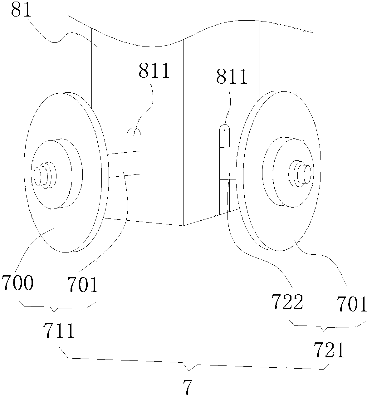
[0029] Example: see Figure 1 to Figure 3 As shown, the gantry line stone cutter provided by the invention includes a base 1, a workbench 2, a workbench drive mechanism 3, a column 4, a beam 5 arranged between the left and right columns, a beam drive mechanism 6, and a beam mounted on the beam. Cutting device 7, cutting device driving mechanism 8 and PLC programmable controller (not shown in the figure);

[0030] see Figure 1 to Figure 3 As shown, the workbench 2 is arranged on the base 1 through the workbench drive mechanism 3. The workbench drive mechanism 3 includes a workbench, a drive motor 31, a pulley shaft 32 arranged on the base, and a pulley 33 arranged at the bottom of the workbench. The table drive motor 31 drives the pulley 33 to move on the pulley shaft 32, and drives the workbench 2 to move on the base 1;

[0031] see Figure 1 to Figure 3 As shown, the column 4 is symmetrically arranged on the left and right sides of the base 1, the beam 5 is erected betwee...


PUM


Abstract

The invention discloses a gantry stone cutting device comprising a base, a bench disposed on the base, a bench drive mechanism, columns symmetrically arranged on left and right sides of the base, a beam arranged between the left and right columns, a beam drive mechanism, a cutting device disposed on the beam, a cutting device drive mechanism, and a PLC (programmable logic controller). The bench drive mechanism drives the bench to move back and forth on the base; the beam drive mechanism drives the beam to ascend and descend along the left and right columns; the cutting device drive mechanism drives the cutting device to shift along the beam. The cutting device comprises a transverse cutting mechanism and a longitudinal cutting mechanism. The cutting device drive mechanism drives a drive belt which meshes with shaft wheels in each of transverse and longitudinal cutting tool sets, and a linkage structure driving the single transverse and longitudinal cutting tool sets to ascend and descend is formed; accordingly, each single tool set can ascend and descend, each single tool set is applicable to cutting according to the shape of stones, and the application range of the gantry stone cutting device is effectively widened.

Description

technical field [0001] The invention relates to a gantry stone-cutting device, which belongs to the technical field of stone manufacturing and cutting according to the International Patent Classification (IPC). Background technique [0002] At present, most line stone cutters in the field of stone processing adopt a single-arm structure, which mainly includes a base, a workbench set on the base, a column standing on one side of the workbench, a beam that can be lifted and set on the column, A cutting device is installed on the crossbeam. This kind of single-arm line stone cutter has a simple structure, poor cutting stability, and a limited moving range of the cutting device, which cannot meet the needs of large-scale stone line cutting. At the same time, the cutting devices in the existing cutting equipment are all The fixed type can only realize the up and down movement through the driving structure, which cannot meet the purpose of cutting according to the special-shaped s...

Claims


Application Information

Patent Timeline
Patent Type & Authority Applications(China)
IPC IPC(8): B28D1/04
Inventor 王银烽
Owner XIAMEN ZHONGHENG MACHINERY MFG
Why Eureka
Try Eureka