
Foam metal filtering type oil separator

A foam metal and oil separator technology, which is applied in separation methods, dispersed particle separation, and dispersed particle filtration, etc., can solve the problems of ineffective return of oil, large airflow pressure drop, and ineffective separation of oil droplets. Enhanced chance of collision, reduced pressure drop, effects of excellent physical properties

Inactive Publication Date: 2015-05-13
TIANJIN UNIV
View PDF7 Cites 0 Cited by
  • Summary
  • Abstract
  • Description
  • Claims
  • Application Information

AI Technical Summary

Problems solved by technology

[0006] The invention aims to solve the technical problem that the oil droplets in the gas cannot be effectively separated, the pressure drop of the gas flow is large, and the separated oil cannot be effectively returned. It provides a foam metal filter oil separator, which is made of foam metal material. Made into a filter facility in the cylinder to effectively improve the separation efficiency

Method used


Image

  • Foam metal filtering type oil separator
  • Foam metal filtering type oil separator
  • Foam metal filtering type oil separator

Examples


Embodiment Construction

[0031] In order to further understand the invention content, characteristics and effects of the present invention, the following examples are given, and detailed descriptions are as follows in conjunction with the accompanying drawings:

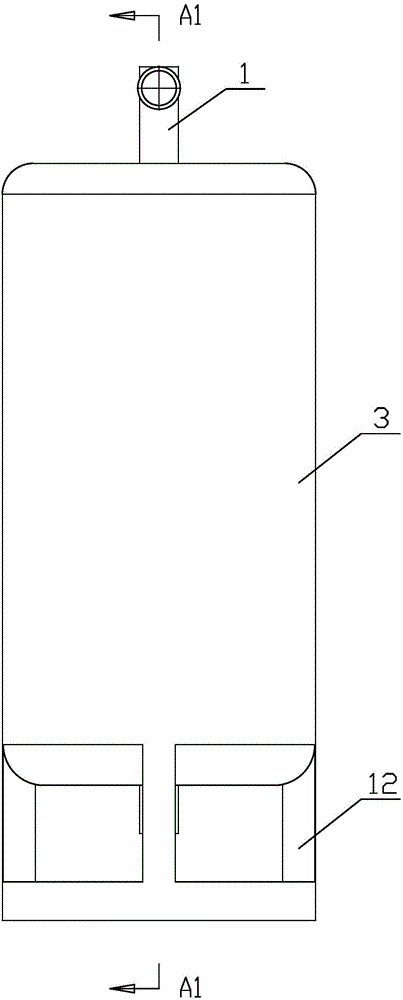
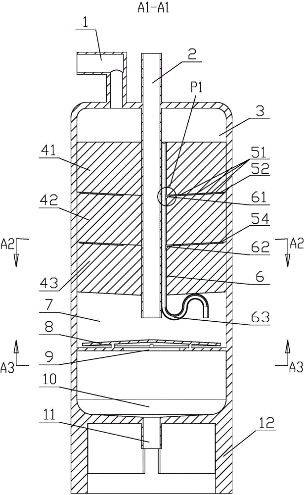
[0032] Such as figure 1 and figure 2 As shown, this embodiment discloses a metal foam filter type oil separator, the metal foam filter type oil separator has a vertical cylindrical outer cylinder 3, the bottom of the outer cylinder 3 is provided with a bracket 12 for supporting the outer cylinder 3 , the top of the outer cylinder 3 is provided with an air inlet port 1 and an air outlet duct 2 . One end of the air inlet port 1 communicates with the top of the outer cylinder 3, and the other end is used for feeding gas mixed with oil droplets. The air outlet duct 2 is located at the center of the top of the outer cylinder 3 , its top end protrudes from the outer cylinder 3 , and its bottom end extends to the cavity 7 in the outer cylinder 3 ...


PUM

PropertyMeasurementUnit
pore sizeaaaaaaaaaa
pore sizeaaaaaaaaaa
pore sizeaaaaaaaaaa

Abstract

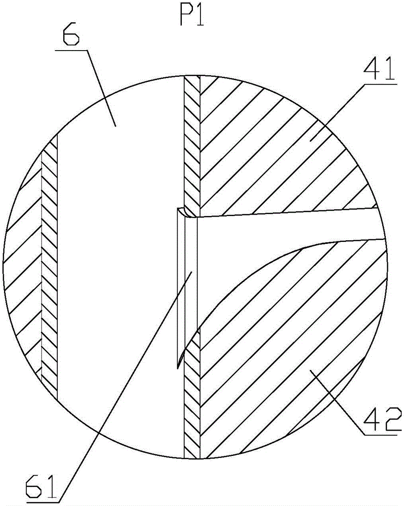
The invention discloses a foam metal filtering type oil separator. The oil separator comprises an outer barrel, wherein an air inlet connector and an air exhausting duct are arranged at the top of the outer barrel; the bottom end of the air exhausting duct extends into a cavity in the outer barrel; the cavity and an oil collecting chamber below the cavity are separated by an oil falling umbrella; an oil falling hole is formed below the oil falling umbrella; an oil outlet is formed in the center of the bottom surface of the oil collecting chamber; three foam metal filtering layers are sequentially arranged in the outer barrel from top to bottom; a plurality of annular oil guiding grooves and centripetal oil guiding grooves are formed between every two foam metal filtering layers; oil guiding pipes, the top ends of which are sealed, extend to openings in the bottom end in the cavity and are provided with oil storing elbows; the oil guiding pipes are respectively communicated with the centripetal oil guiding grooves. As the oil separator is used, airflows mixed with oil drops are filtered by the three foam metal filtering layers, the airflows in which the majority of oil drops are filtered are exhausted by the air exhausting duct while the filtered oil drops fall onto the oil falling umbrella through the annular oil guiding grooves, the centripetal oil guiding grooves and the oil guiding pipes, then reach the oil collecting chamber through the oil falling hole and finally are discharged through the oil outlet.

Description

technical field [0001] The present invention relates to an oil separator, and more specifically relates to a device installed between the outlet of the compressor and the inlet of the condenser in the refrigeration system, which can separate and recover the oil droplets mixed in the high-pressure gas . Background technique [0002] In the refrigeration system, the compressed refrigerant is in a superheated state of high pressure and high temperature. Because of its fast flow rate and high temperature when it is discharged, and part of the lubricating oil on the cylinder wall is inevitably discharged into oil vapor and oil droplets and particles together with the refrigerant vapor due to the high temperature. The oil separator is a device installed between the compressor outlet and the condenser inlet of the refrigeration system, which can separate and recover the oil droplets mixed in the high-pressure mixed gas. [0003] According to the principle and internal structure, ...

Claims


Application Information

Patent Timeline
Patent Type & Authority Patents(China)
IPC IPC(8): B01D46/00
Inventor 李敏霞夏博睿董克勤王派赵健福王昊炜
Owner TIANJIN UNIV
Learn More