
Dual-path 3D laparoscope and dual-path 3D laparoscopic system

A laparoscopic and 3D technology, applied in the field of laparoscope and laparoscopic system, can solve the problems of limited depth of field and three-dimensional sense, stagnation in the theoretical research stage, not meeting the shortest requirements, etc., to reduce medical costs, easy to use, and enhance three-dimensional three-dimensional effect

Inactive Publication Date: 2014-04-23
JIANGSU KEQIN PHOTOELECTRIC SCI & TECH
View PDF7 Cites 9 Cited by
  • Summary
  • Abstract
  • Description
  • Claims
  • Application Information

AI Technical Summary

Problems solved by technology

[0005] The dual-channel 3D endoscope has not formed a real commercial product for a long time at home and abroad, mainly due to the technical difficulty and high cost, and the long-term stagnation in the theoretical research stage
There are also individual units in China such as Changchun University of Science and Technology and Nankai University (Patent Publication No. CN101518438A) who have done research and experiments in this area, but have not been able to form products due to various difficulties or mechanism reasons.
For example, the depth of field of the endoscope developed by Nankai University is 20-120mm, and the working length of the outer tube is 319mm. From a medical point of view, the above two indicators do not meet the minimum requirements of traditional laparoscopy internationally, and the focal length is 20-25mm. If it is larger than 5mm, it also limits the depth of field and three-dimensional sense, and is not suitable for obese patients. At the same time, the endoscope uses a traditional xenon cold light source and a 5-10m light guide, which consumes high energy and increases medical costs.

Method used


Image

  • Dual-path 3D laparoscope and dual-path 3D laparoscopic system
  • Dual-path 3D laparoscope and dual-path 3D laparoscopic system
  • Dual-path 3D laparoscope and dual-path 3D laparoscopic system

Examples


Embodiment

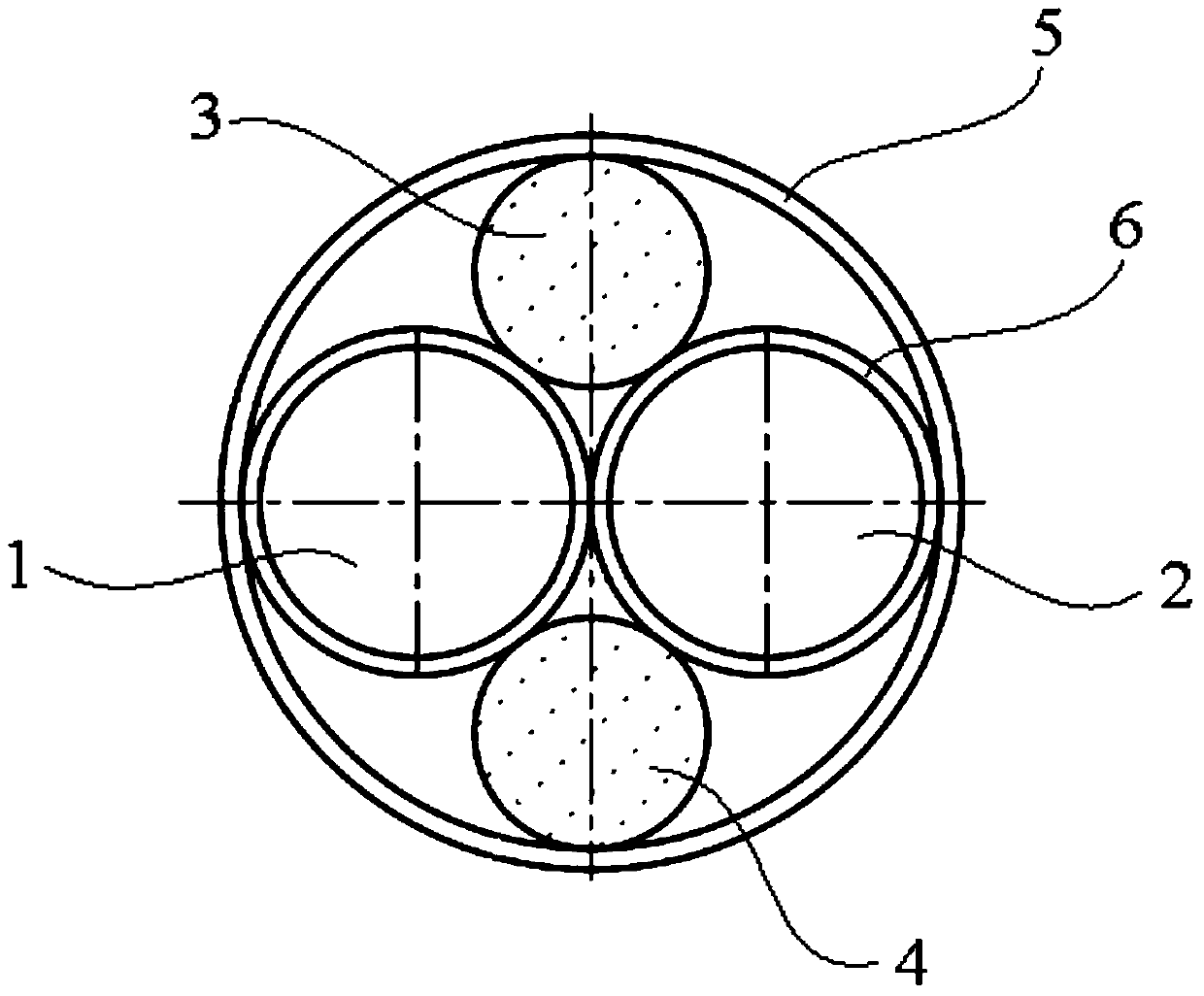
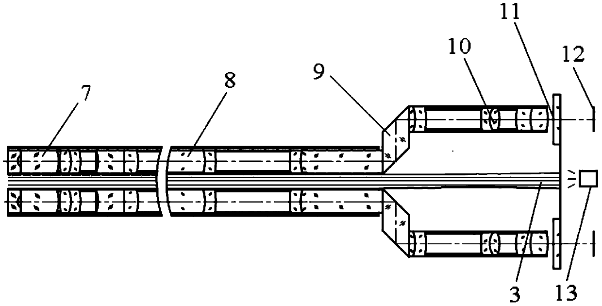
[0018] A double-path 3D laparoscope, comprising a left optical path 1, a right optical path 2, an upper illuminating fiber 3, a lower illuminating optical fiber 4 and an outer tube 5; the left optical path 1 and the right optical path 2 are composed of exactly the same structure, and the front The objective lens 7, the intermediate image transmission rod mirror 8, the rhomboid prism 9, the rear objective lens 10, the protective glass 11 and the imaging surface 12 are arranged in the inner tube 6 in sequence; the left optical path 1 and the right optical path 2 are arranged along the axial direction of the outer tube They are arranged in parallel in the outer tube 5; the upper illuminating optical fiber 3 is arranged in the upper cavity between the left optical path 1, the right optical path 2 and the outer tube 5; the lower illuminating optical fiber 4 is arranged in the left optical path 1, the right optical path In the lower cavity between the optical path 2 and the outer tub...


PUM


Abstract

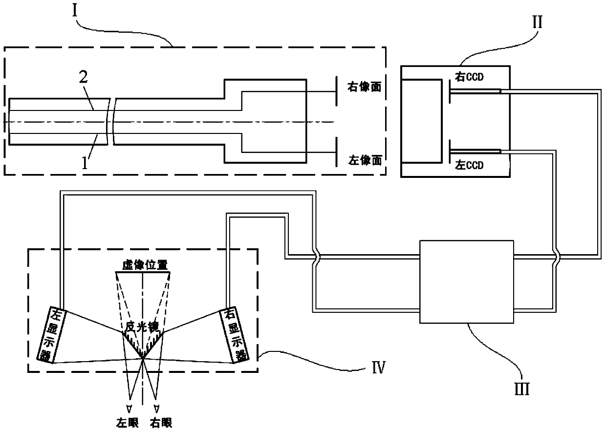
The invention relates to a dual-path 3D laparoscope and a dual-path 3D laparoscopic system, relates to the field of laparoscopes and laparoscopic systems, and solves the problems that presently, foreign 3D laparoscopes are high in cost and domestic 3D laparoscopes do not meet the using standards. The dual-path 3D laparoscope comprises a left light path, a right light path, an upper lighting fiber, a lower lighting fiber, and an outer tube; the left light path and the right light path composed of the full-same structures are formed by sequentially arranging a front objective, a middle image transmission rod lens, a rhombic prism, a rear objective, protective glass and an imaging face in an inner tube. The dual-path 3D laparoscopic system is composed of the dual-path 3D laparoscope, a dual-path CCD camera, an image data processor, and a multi-path precision 3D display. Depth of field of the dual-path 3D laparoscope is 10-180mm, operating length of the outer tube is 330mm, and the depth of field and the operating length both meet the international general requirement of traditional laparoscope for the smallest length; the dual-path 3D laparoscopic system is low in cost and convenient to use.

Description

Technical field: [0001] The present invention relates to the field of laparoscopes and laparoscopic systems. Background technique: [0002] Traditional minimally invasive laparoscopic surgery can only provide doctors with two-dimensional images. The lack of depth information in the field of view makes it difficult for doctors to judge the depth distribution of intra-abdominal organs. Therefore, doctors need long-term repeated training to be competent for this kind of surgery. Even skilled doctors It is also easy to misuse during the operation and hurt the patient. [0003] Dual-channel 3D laparoscopy is to apply three-dimensional video technology to minimally invasive surgery, creating reliable visual conditions close to reality for doctors, revolutionaryly improving the accuracy of surgery, greatly shortening the training period for minimally invasive surgery doctors, and greatly reducing the The tension and fatigue intensity during the doctor's operation also greatly redu...

Claims


Application Information

Patent Timeline
Patent Type & Authority Applications(China)
IPC IPC(8): A61B1/313A61B1/05A61B1/07
Inventor 韩沁驰张学典俞锡鹏
Owner JIANGSU KEQIN PHOTOELECTRIC SCI & TECH
Learn More