
an oscillating circuit

An oscillating circuit, charging and discharging technology, applied in power oscillators, electrical components, etc., can solve the problem of high energy consumption of oscillating circuits, and achieve the effects of reducing circuit energy consumption, simplifying circuit structure, and reducing control power consumption

Active Publication Date: 2016-08-24
SHANGHAI HUAHONG GRACE SEMICON MFG CORP
View PDF4 Cites 0 Cited by
  • Summary
  • Abstract
  • Description
  • Claims
  • Application Information

AI Technical Summary

Problems solved by technology

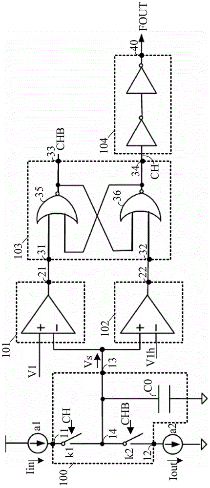
[0014] In order to effectively suppress the influence of PVT (Process Voltage Temperature) deviation on the circuit oscillation frequency, the oscillation circuit in the prior art needs at least two comparison units, and the comparison units consume a lot of energy to achieve a higher comparison rate
Therefore, the energy consumption of the oscillating circuit in the prior art is relatively high

Method used


Image

  • an oscillating circuit
  • an oscillating circuit
  • an oscillating circuit

Examples


Embodiment approach

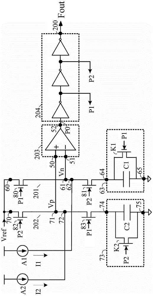
[0075] continue to refer figure 2 , the first capacitive unit 63 specifically includes a first capacitive element C1 and a first control transistor K1, one end (namely node 64) of the first capacitive element C1 is connected to the second input node 62 through the second switch transistor 81, and the other end ( That is, the node 65) is grounded, and the first control tube K1 is connected in parallel to both ends of the first capacitive element C1, that is, one end of the first control tube K1 is connected to the node 64, and the other end is connected to the node 65, and the first control tube K1 The control terminal is connected to the third signal P1.

[0076] The second capacitive unit 73 includes a second capacitive element C2 and a second control transistor K2. One end (ie node 74) of the second capacitive element C2 is connected to the fourth input node 72 through a fourth switch tube 83, and the other end (ie Node 75) is grounded, and the second control tube K2 is co...


PUM


Abstract

The invention relates to an oscillating circuit. The oscillating circuit comprises a first output terminal and also comprises a first charge and discharge unit, a second charge and discharge unit and a comparing unit; the comparing unit comprises a positive terminal, a negative terminal and a second output terminal which is used for outputting comparison signals; the second output terminal is connected with a first output terminal; the first charge and discharge unit is used for being charged and outputting first levels to the negative terminal when the comparison signals are first signals; the second charge and discharge unit is used for being charged and outputting second levels to the positive terminal when the comparison signals are second signals; according to the comparing unit, the positive terminal is connected with the reference voltage when the comparison signals are the first signals and the negative terminal is connected with the reference voltage when the comparison signals are the second signals; the first signals and the second signals are inversion signals with each other. According to the oscillating circuit, the energy consumption can be reduced.

Description

technical field [0001] The invention relates to the field of integrated circuits, in particular to an oscillation circuit. Background technique [0002] In large-scale digital integrated circuits, the clock signal has become an essential part. The clock signal can be generated by the oscillating signal output by the oscillating circuit. In these digital system circuits, there are three commonly used oscillating circuits: ring oscillating circuit, crystal oscillating circuit and RC (resistor-capacitor) oscillating circuit. [0003] The ring oscillation circuit has a wide oscillation range and high stability, but the ring oscillation circuit is sensitive to power supply noise and has a large layout size. The frequency of the crystal oscillator circuit is very accurate, and the work is stable. Its accuracy is only related to the natural frequency of the selected crystal device. However, the power consumption of the crystal oscillator circuit is large and the price is high, so ...

Claims


Application Information

Patent Timeline
Patent Type & Authority Patents(China)
IPC IPC(8): H03B5/20
Inventor 陈丹凤
Owner SHANGHAI HUAHONG GRACE SEMICON MFG CORP
Learn More