
Discharge protection circuit and its control method

A discharge protection and control method technology, applied in safety/protection circuits, battery over-discharge protection, emergency protection circuit devices, etc., can solve the problems of battery pack consumption, discharge power reduction, energy waste, etc., to reduce control power consumption, The effect of increasing the discharge capacity

Active Publication Date: 2018-10-02
NANJING CHERVON IND
View PDF7 Cites 0 Cited by
  • Summary
  • Abstract
  • Description
  • Claims
  • Application Information

AI Technical Summary

Problems solved by technology

[0002] In the discharge circuit composed of battery packs and electric tools, especially the discharge circuit composed of multi-cell, high-voltage, and high-heat-generating battery packs, in order to realize discharge protection, an MCU chip for intelligent protection is often set up to support the discharge circuit. The PCBA component of the MCU chip, but because the MCU chip has a high clock frequency and it needs to perform multiple detections and controls, a large part of the power of the battery pack is consumed on the PCBA component for intelligent control
When the discharge circuit discharges with a small current for a long time, the discharge power is greatly reduced, resulting in waste of energy, and it is difficult to meet user needs

Method used


Image

  • Discharge protection circuit and its control method
  • Discharge protection circuit and its control method

Examples


Embodiment Construction

[0018] The present invention will be specifically introduced below in conjunction with the accompanying drawings and specific embodiments.

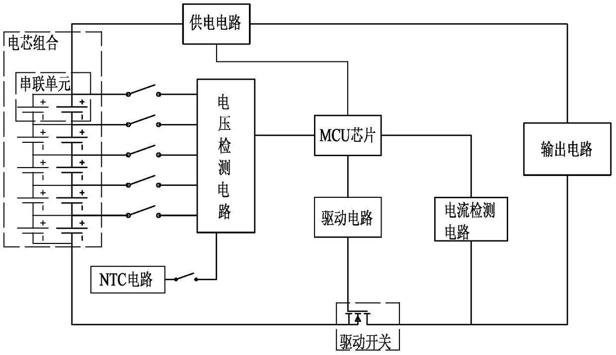
[0019] refer to figure 1 As shown, the discharge protection circuit of the present invention includes: a cell combination, which includes more than one cell, a power supply circuit, an output circuit, an MCU chip, a voltage detection circuit, an NTC circuit, a current detection circuit, a drive circuit and a drive switch.

[0020] Wherein, the power supply circuit, the output circuit and the battery cells are combined to form a series connection, and the MCU chip is respectively electrically connected to the voltage detection circuit, the drive circuit, and the current detection circuit.

[0021] The power supply circuit is used to realize the adjustment of voltage and current, so that the MCU chip and the output circuit can obtain the required power supply.

[0022] The voltage detection module is electrically connected to the cell com...


PUM


Abstract

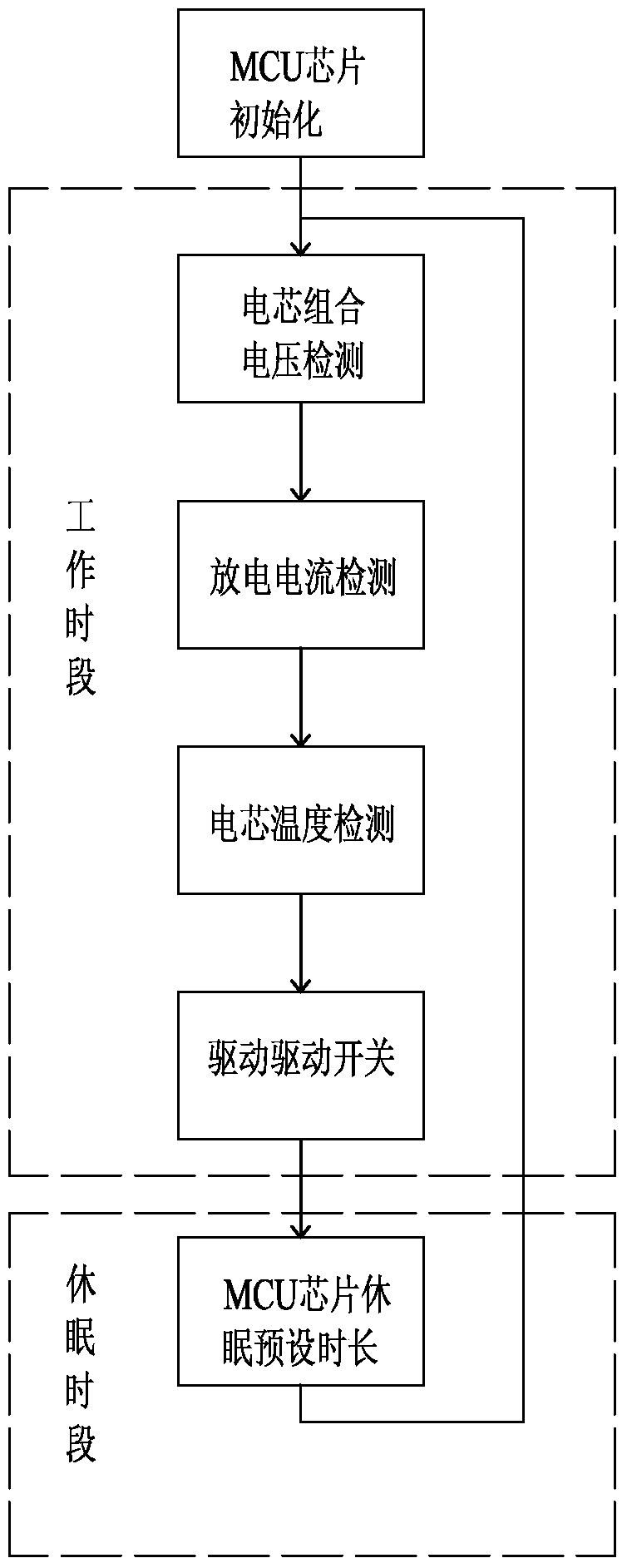
The invention discloses a discharge protection circuit and a control method thereof, wherein the discharge protection circuit includes: a cell combination, the cell combination includes more than one cell, a power supply circuit, an output circuit, an MCU chip, a voltage detection circuit, and an NTC circuit , a current detection circuit, a drive circuit, and a drive switch; the power supply circuit, the output circuit, and the battery cell are connected in series; the MCU chip is electrically connected to the voltage detection circuit, the drive circuit, and the current detection circuit; the voltage detection module is connected to the battery cell The combination and the NTC circuit form an electrical connection; the control method at least includes a discharge process in which the discharge protection circuit is discharged at 0.2 times the nominal power per hour, and in this process, the MCU chip is periodically dormant; the present invention is beneficial The advantage is that by periodically making the MCU chip dormant, on the basis of realizing the discharge protection of the battery pack, it also realizes the purpose of reducing the control power consumption and increasing the discharge power.

Description

technical field [0001] The invention relates to a circuit and a control method thereof, in particular to a discharge protection circuit and a control method thereof. Background technique [0002] In the discharge circuit composed of battery packs and electric tools, especially the discharge circuit composed of multi-cell, high-voltage, and high-heat-generating battery packs, in order to realize discharge protection, an MCU chip for intelligent protection is often set up to support the discharge circuit. The PCBA component of the MCU chip, but because the MCU chip has a high clock frequency and it needs to perform multiple detections and controls, a large part of the power of the battery pack is consumed on the PCBA component for intelligent control. When the discharge circuit discharges with a small current for a long time, the discharge power is greatly reduced, resulting in waste of energy, and it is difficult to meet user needs. Contents of the invention [0003] In or...

Claims


Application Information

Patent Timeline
Patent Type & Authority Patents(China)
IPC IPC(8): H02H7/18
CPCH02J7/0063H02J7/0029H02J7/00306H02J7/00714H02J7/007194H02J7/007182
Inventor 高庆耿正
Owner NANJING CHERVON IND
Learn More