
Slope compensation circuit applied to current mode DC-DC converter

A technology of slope compensation and converter, which is applied in the direction of high-efficiency power electronic conversion, output power conversion device, electrical components, etc., can solve the problem of increasing converter chip area and controlling circuit power consumption, large circuit scale, and voltage-current converter Complicated structure and other issues, to achieve the effect of reducing power consumption, reducing chip area, and reducing circuit scale

Pending Publication Date: 2022-08-05
伯恩半导体(无锡)有限公司
View PDF0 Cites 0 Cited by
  • Summary
  • Abstract
  • Description
  • Claims
  • Application Information

AI Technical Summary

Problems solved by technology

[0004] The traditional slope compensation scheme requires two additional voltage-current converters to achieve voltage superposition. The structure of the voltage-current converter is relatively complex, which makes the circuit scale larger, which will greatly increase the chip area of ​​the converter and the power consumption of the control circuit.

Method used


Image

  • Slope compensation circuit applied to current mode DC-DC converter
  • Slope compensation circuit applied to current mode DC-DC converter
  • Slope compensation circuit applied to current mode DC-DC converter

Examples


Embodiment 1

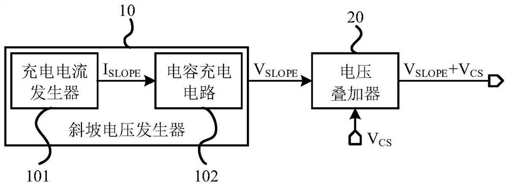
[0040] See image 3 , image 3 It is a structural block diagram of a slope compensation circuit provided by an embodiment of the present invention. As shown in the figure, the slope compensation circuit of this embodiment includes a slope voltage generator 10 and a voltage stacker 20, wherein the slope voltage generator 10 is used for Generate ramp voltage V SLOPE ; the voltage superimposed 20 is used to ramp the voltage V SLOPE with the inductor current sampling voltage V CS superimposed, and output the superimposed signal V SLOPE +V CS , to achieve slope compensation.

[0041] The ramp voltage generator 10 includes a connected charging current generator 101 and a capacitor charging circuit 102; the output terminal of the capacitor charging circuit 102 is connected to the input terminal of the voltage stacker 20; the charging current generator 101 is used to generate the charging current I SLOPE ; Capacitor charging circuit 102 is used for charging current I according t...


PUM


Abstract

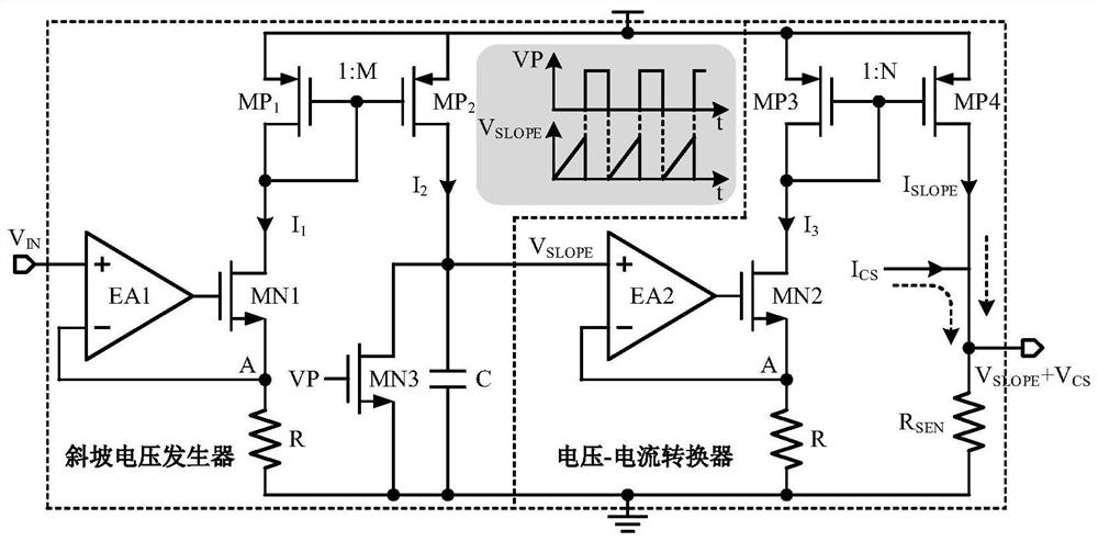
The invention relates to a slope compensation circuit applied to a current mode DC-DC converter, and the circuit comprises a slope voltage generator which is used for generating a slope voltage VSLOPE; the voltage superimposer is used for superimposing the slope voltage VSLOPE and the inductive current sampling voltage VCS and outputting a superimposed signal VSLOPE + VCS; wherein the ramp voltage generator comprises a charging current generator and a capacitor charging circuit; the charging current generator is used for generating charging current ISLOPE; and the capacitor charging circuit charges the capacitor by using the charging current ISLOPE to obtain a ramp voltage VSLOPE. According to the slope compensation circuit provided by the invention, direct superposition of the slope voltage VSLOPE and the inductive current sampling voltage VCS is realized by utilizing the electrical characteristics of the capacitor, and a method for realizing voltage superposition by needing two extra voltage-current converters in a traditional slope compensation circuit is replaced. The circuit structure is simplified, the circuit scale is reduced, the area of a converter chip is reduced, and the power consumption of the control circuit is reduced.

Description

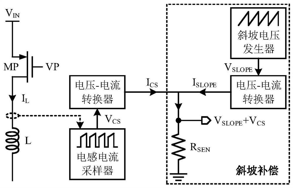
technical field [0001] The invention belongs to the technical field of integrated circuit design, and in particular relates to a slope compensation circuit applied to a current mode DC-DC converter. Background technique [0002] In the design of DC-DC converters, the current mode has the advantages of simple frequency compensation and fast transient response speed compared with the voltage mode. However, when the duty cycle is greater than 50%, problems such as sub-harmonic oscillation may occur in the current mode, and slope compensation needs to be added to the circuit to ensure the normal operation of the DC-DC converter. [0003] Typically, slope compensation is accomplished by superimposing a small fixed voltage ramp on the sampled voltage ramp of the DC-DC converter inductor or switch. The implementation block diagram of traditional slope compensation is as follows figure 1 shown, the ramp voltage generator and inductor current sampler generate a ramp voltage V SLOP...

Claims


Application Information

Patent Timeline
Patent Type & Authority Applications(China)
IPC IPC(8): H02M1/00H02M1/14
CPCH02M1/0048H02M1/143Y02B70/10
Inventor 张磊
Owner 伯恩半导体(无锡)有限公司
Learn More