
Method and device for detecting metal oxide arrester resistive current

A resistive current and detection device technology, applied in the direction of measuring devices, measuring current/voltage, instruments, etc., can solve problems affecting the safe operation of the power grid, voltage transformer burnout, secondary short circuit, etc., and achieve good temperature characteristics and anti-electromagnetic Interference ability, guaranteed accuracy and authenticity, easy-to-operate effects

Active Publication Date: 2014-04-16
STATE GRID CORP OF CHINA +2
View PDF3 Cites 12 Cited by
  • Summary
  • Abstract
  • Description
  • Claims
  • Application Information

AI Technical Summary

Problems solved by technology

[0004] At present, the following conventional methods are used to measure the resistive current of metal oxide arresters in online monitoring or live tests: the full leakage current during operation is obtained from the grounding wire of the metal oxide arrester, and the current of the metal oxide arrester is obtained from the same-phase voltage transformer. The terminal voltage, the terminal voltage is used as the reference vector, and the resistive current in the full current is separated by comparing the phase of the full current and the terminal voltage, so as to judge the operation status of the arrester according to the change of the resistive current component; however, the measurement of the terminal voltage It is necessary to frequently operate the secondary terminal of the voltage transformer, which may easily cause its secondary short circuit, and even cause the voltage transformer to burn out, affecting the safe operation of the power grid. In order to ensure the safety of the power grid and equipment, many power companies even stipulate that testers are not allowed to operate the voltage The secondary terminal of the transformer brings inconvenience to the measurement

Method used


Image

  • Method and device for detecting metal oxide arrester resistive current
  • Method and device for detecting metal oxide arrester resistive current
  • Method and device for detecting metal oxide arrester resistive current

Examples


Embodiment Construction

[0022] Attached below Figure 1~2 The present invention is further described with embodiment:

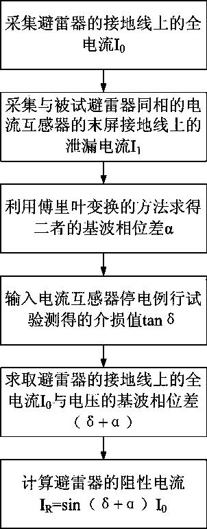
[0023] Depend on figure 1 As can be seen from the shown embodiment, the steps of the method adopted in this embodiment are as follows:

[0024] Step 1. Collect parameter current:

[0025] Collect the full current signal I on the ground wire of the metal oxide arrester 0 , the leakage current signal I is collected on the last screen grounding wire of the current transformer in the same phase as the metal oxide arrester under test 1 ;

[0026] Step 2, the resistive current I in the full current signal I R seperate:

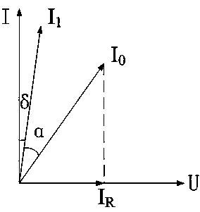
[0027] According to the dielectric loss factor measured by the current transformer power failure test in the same phase as the metal oxide arrester measured, it is tanδ, and the leakage current signal I is known. 1 The phase angle with the terminal current of the metal oxide arrester is δ; at the same time, the leakage current signal I is obtained by Fourier transf...


PUM


Abstract

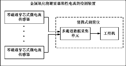
The invention discloses a method and device for detecting a metal oxide arrester resistive current. The method includes the following steps that 1, a parameter current is collected; 2, on the basis that the dielectric loss factor, tested in a black-out test and being the same with that of a metal oxide arrester, of a current transformer is tan delta, the phase included angle between a leakage current signal I1 and an end current of the current transformer is delta; the phase difference between the fundamental wave of the leakage current signal I1 and the fundamental wave of a full current signal I0 is alpha; through calculation, the resistive current IR satisfies the following formula that IR is equal to sin (delta+alpha)* I0. The device comprises a signal connecting cable, a portable measuring instrument and more than two zero flux core-through-type micro-current sensors. The method and device for detecting the metal oxide arrester resistive current have the advantages that under the condition that a terminal voltage is not measured, accurate measurement of the metal oxide arrester resistive current is achieved, a secondary terminal of a voltage transformer does not need to be operated, the detection safety and the detection stability are improved, operation is easy, measurement is accurate, and field operation can be performed easily.

Description

technical field [0001] The invention relates to a method and a device for detecting the resistive current of a metal oxide lightning arrester, belonging to the technical field of condition maintenance of electrical equipment. Background technique [0002] Metal oxide surge arresters have superior overvoltage protection characteristics, such as no freewheeling, light operating load, strong resistance to repeated actions, and large flow capacity, etc., and have been widely used in power systems. Under the action of the working voltage, the leakage current flowing through the metal oxide arrester is only microampere level. However, since there is no gap in the metal oxide arrester, current will always flow through the valve plate, and the valve plate will deteriorate under long-term action, causing changes in the resistance characteristics, resulting in an increase in the leakage current flowing through the valve plate. In addition, due to the poor structure and poor sealing o...

Claims


Application Information

Patent Timeline
IPC IPC(8): G01R19/00
Inventor 高树国陈志勇潘瑾范辉刘宏亮孙祎赵建利杜大全
Owner STATE GRID CORP OF CHINA
Learn More