Fin structure of heat exchanger

A heat exchanger and fin technology, applied in the field of heat exchanger fin structure, can solve the problems of large heat exchanger tube resistance and poor heat dissipation effect

Inactive Publication Date: 2014-04-16
无锡高晟成型科技有限公司
View PDF0 Cites 0 Cited by
  • Summary
  • Abstract
  • Description
  • Claims
  • Application Information

AI Technical Summary

Problems solved by technology

As a compact heat exchanger, the finned tube heat exchanger is widely used in power, chemical industry, refrigeration and other industrial fields, and has high heat exchange efficiency. Usually, its base tube is a round tube. After research, it is found that the existing circular tube heat exchanger has large tube resistance and poor heat dissipation effect

Method used


Image

  • Fin structure of heat exchanger

Examples


Embodiment Construction

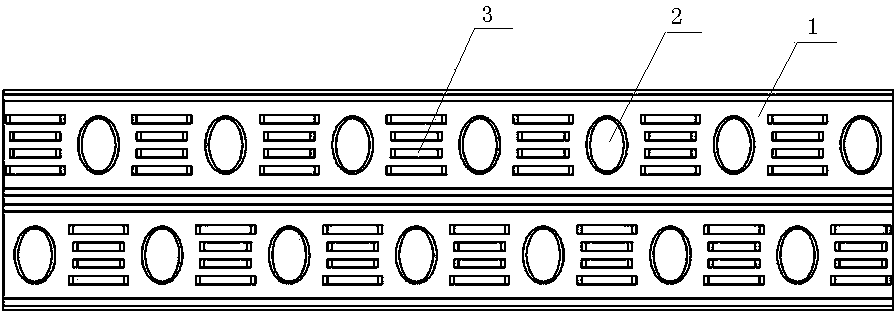
[0008] See figure 1 , a heat exchanger fin structure, which includes a heat exchanger fin body 1, the heat exchanger fin body 1 is provided with an elliptical through hole 2, and the heat exchanger fin body 1 is provided with horizontal and vertical holes respectively A plurality of through holes, and a plurality of bridge grooves 3 are arranged between the 2 transverse oval through holes.

[0009] Elliptical tubes have less drag loss. Compared with the conventional circular tube heat exchanger, the main difference between the elliptical tube heat exchanger is that the circular tube is replaced by an elliptical tube. Due to the good aerodynamic characteristics of the elliptical tube, the flow direction of the fluid is similar to the streamline, the air can flow smoothly from the surface, and the separation point of the airflow and the tube is moved back, which reduces the vortex area behind the tube, thereby reducing the air resistance, which is the same as Compared with rou...


PUM


Abstract

The invention provides a fin structure of a heat exchanger. The fin structure reduces pipe resistance of the heat exchanger and improves the heat dissipation efficiency. The fin structure comprises a fin body of the heat exchanger and a through hole is formed in the fin body of the heat exchanger. The fin structure of the heat exchanger is characterized in that the through hole is oval.

Description

technical field [0001] The invention relates to the technical field of heat exchangers, in particular to a heat exchanger fin structure. Background technique [0002] As a process equipment in heat transfer, heat exchangers are widely used in industrial fields. With the increasing shortage of various energy sources, the rational design, operation and improvement of heat exchangers are very important to save money, materials, energy and space. As a compact heat exchanger, the finned tube heat exchanger is widely used in power, chemical industry, refrigeration and other industrial fields, and has high heat exchange efficiency. Usually, its base tube is a round tube. It is found through research that the existing circular tube heat exchanger has large tube resistance and poor heat dissipation effect. Contents of the invention [0003] In view of the above problems, the present invention provides a heat exchanger fin structure, which reduces the pipe resistance of the heat e...

Claims


Application Information

Patent Timeline
Patent Type & Authority Applications(China)
IPC IPC(8): F28F3/02
Inventor 薛燕凤
Owner 无锡高晟成型科技有限公司
Why Eureka
Try Eureka