Emulsion explosive continuous filling and conveying piston pump

A technology of emulsified explosives and piston pumps, applied in explosives, explosives processing equipment, offensive equipment, etc., can solve the problems of reducing speed, production capacity, reducing performance damage, and occupying a large area, so as to achieve low working rated speed and ensure performance , the effect of pressure stabilization

Inactive Publication Date: 2014-05-21
黄文明 +1
View PDF3 Cites 0 Cited by
  • Summary
  • Abstract
  • Description
  • Claims
  • Application Information

AI Technical Summary

Problems solved by technology

The above structure will greatly damage the performance of emulsion explosives during the process of feeding, conveying and discharging medium and low-temperature small-diameter emulsion explosives. Loading and conveying bring great difficulties; for this reason, it can only reduce the degree of performance damage at the cost of reducing speed, production capacity and efficiency
Emulsion explosives are in a high-temperature state above 90°C. Although the fluidity is significantly improved, the delivery temperature of the emulsion explosive matrix is ​​around 110°C. Its production efficiency is a problem, but it also brings problems that the high-temperature wrapped emulsion explosive rolls are not easy to cool, and the cooling facilities require a large investment and occupy a large area.
For this reason, none of the existing filling and conveying equipment can well realize the continuous quantitative filling and conveying functions of medium and low temperature emulsion explosives with small diameter and large flow rate.

Method used


Image

  • Emulsion explosive continuous filling and conveying piston pump
  • Emulsion explosive continuous filling and conveying piston pump
  • Emulsion explosive continuous filling and conveying piston pump

Examples


Embodiment Construction

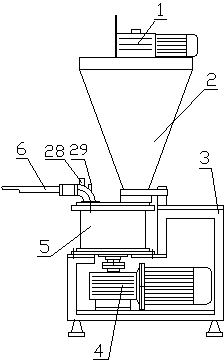
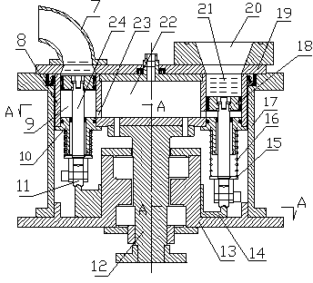
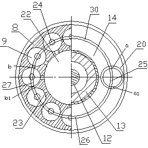
[0019] Such as figure 1 A piston pump for continuously filling and conveying emulsion explosives shown includes a frame 3, a feed hopper 2, a feeder 1, a piston pump body 5, a rotating power mechanism 4, and a discharge nozzle 6, and the piston pump body passes through The base 13 on it is fixedly installed on the frame; the feed hopper 2 is fixedly connected to the feeding interface 20 of the piston pump body, and can communicate with the cylinder hole in the piston pump body, and the feeder is arranged on On the feed hopper, the discharge nozzle 6 is fixedly connected to the discharge interface 7 on the piston pump body and communicates with the cylinder hole 9 rotated to the left end of the horizontal center line in the piston pump body; the rotary power mechanism 4 It is connected with the main shaft 12 on the pump body 5 of the piston pump to provide rotational power for the main shaft; in order to facilitate precise control and safe operation, a pressure measuring elemen...


PUM


Abstract

The invention discloses an emulsion explosive continuous filling and conveying piston pump, comprising a rack (3), a rotary power mechanism (4), a piston pump body (5), a feeding mechanism and a discharging mechanism, wherein the rotary power mechanism (4) is positioned in the rack, the piston pump body (5) is supported on the rack and connected with the rotary power mechanism, and the feeding mechanism and the discharging mechanism are positioned on the rack; the piston pump body (5) comprises an outer shell, a main shaft (12), a cylinder body (8) and a piston (18), wherein the outer shell comprises a base (13), an outer barrel (17) and a cover plate (19), the main shaft is movably arranged on the base and connected with the rotary power mechanism, the cylinder body is fixedly arranged on the upper end of the main shaft, annular uniformly-distributed cylinder holes (9) are arranged in the cylinder body at intervals, pistons is hermetically arranged in the cylinder holes, a spring (16) is arranged between the cylinder body and a spacing plate, and a guide wheel (11) is arranged on the spacing plate and supported on a closed-loop lifting guide rail (14). The emulsion explosive continuous filling and conveying piston pump has the advantages of stable flow and pressure and low rated rotary speed for working, and can realize small-pipe diameter large-yield continuous filling and conveyance of the emulsion explosive.

Description

technical field [0001] The invention relates to an emulsion explosive production equipment, in particular to a medium- and low-temperature emulsion explosive small-diameter, large-flow continuous quantitative loading and conveying equipment. Background technique [0002] The emulsion explosive matrix is ​​highly dispersed oxidant aqueous solution in the combustible oil phase material in the form of emulsification process, and the emulsion explosive is formed after adding a sensitizer to it. At present: the equipment used for the filling and transportation of emulsion explosives includes single screw pump, twin screw pump, elliptical screw pump, gear pump, vane pump, etc. The feeding, conveying and discharging of emulsion explosives all rely on the rotation of mechanical threads and blades The thrust of shearing and stirring achieves the purpose of feeding, conveying and discharging. Since the emulsion explosive has the characteristics of high viscosity and poor fluidity at ...

Claims


Application Information

Patent Timeline
Patent Type & Authority Patents(China)
IPC IPC(8): C06B21/00
Inventor 黄海宏黄文明
Owner 黄文明
Why Eureka
Try Eureka