Charging method, charging circuit and electronic device
A technology of electronic equipment and charging circuit, which is applied in the electronic field to achieve the effect of reducing charging time, wide application and ensuring safety performance.
- Summary
- Abstract
- Description
- Claims
- Application Information
AI Technical Summary
Problems solved by technology
Method used
Image
Examples
Embodiment 1
[0038] This embodiment provides a charging method, which is applied to an electronic device equipped with a battery, wherein the electronic device can be an MP4, a mobile phone, etc. In the following description, the electronic device will be a mobile phone as an example. Detailed description.
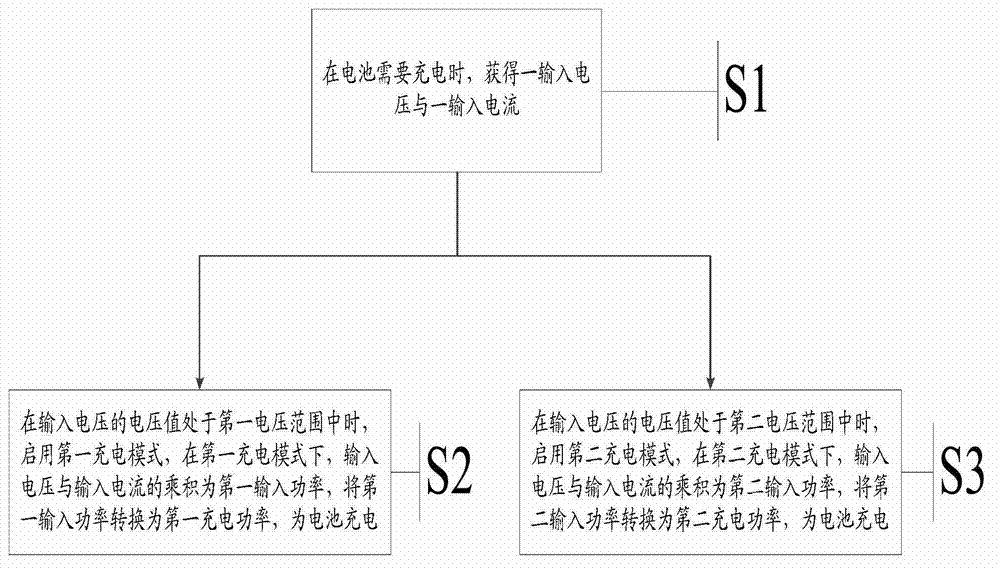
[0039] Please refer to figure 1 , figure 1 It is a flow chart of the charging method provided in this embodiment, and the method includes:
[0040] S1: Obtain an input voltage and an input current when the battery needs to be charged;
[0041] S2: When the voltage value of the input voltage is in the first voltage range, enable the first charging mode, in the first charging mode, the product of the input voltage and the input current is the first input power, and convert the first input power into the second - Charging power, to charge the battery;
[0042] S3: When the voltage value of the input voltage is in the second voltage range, wherein the minimum value of the second voltag...
Embodiment 2
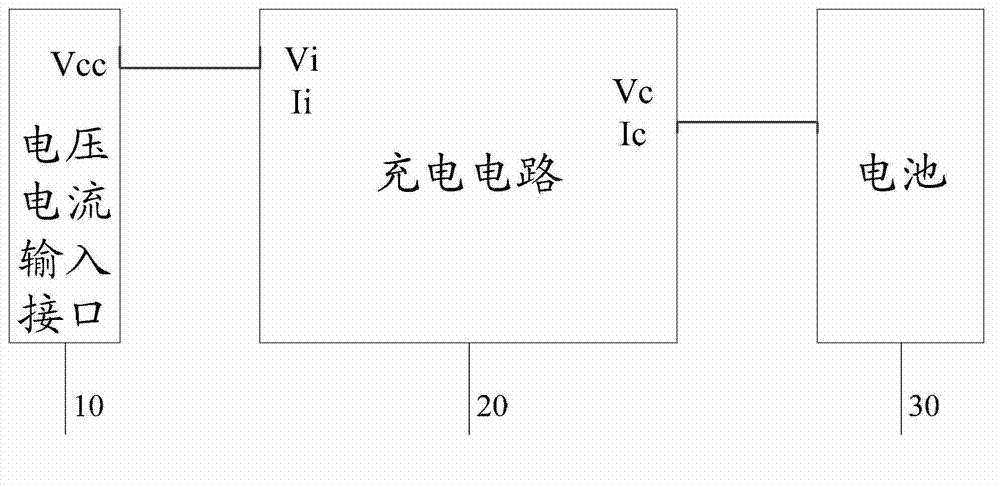
[0073] This embodiment provides a charging circuit, which is respectively connected to the voltage and current input interface 10 and the battery 30 in an electronic device. Please refer to figure 2 , figure 2 It is a schematic diagram of the charging circuit provided in this embodiment. The charging circuit 20 can convert the input voltage Vi and input current Ii input from the voltage and current input interface 10 into the charging voltage Vc and charging current Ic of the battery 30 .
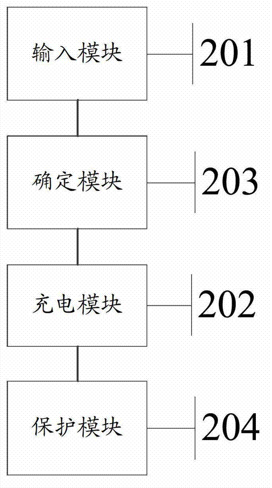
[0074] Please refer to image 3 , image 3 is a functional block diagram of the charging circuit provided in this embodiment, it should be noted that, image 3 The mutual connection relationship between each functional module is just to describe the circuit in the embodiment of the present invention in detail, and can not be used for limiting the present invention, and this charging circuit 20 comprises:
[0075] The input module 201 is connected to the voltage and current input interf...
Embodiment 3
[0096] This embodiment provides an electronic device, please refer to Image 6 , Image 6 It is a functional block diagram of the electronic device provided in this embodiment, the electronic device is equipped with a battery 304, and the electronic device includes:
[0097] Chassis 301;
[0098] The circuit board 302 is arranged in the casing 301;
[0099] The charging circuit 303 is arranged on the circuit board 302 and connected with the battery 304 .
[0100] The charging circuit 303 in this embodiment, that is, the charging circuit 30 in the second embodiment above, has described the working process of the charging circuit 30 in detail in the previous embodiment, so those skilled in the art can clearly To understand the structure and implementation process of the electronic device in this embodiment, for the sake of brevity of the description, details are not repeated here.
[0101] The above-mentioned technical solutions in the embodiments of the present invention ha...
PUM
 Abstract
Description
Claims
Application Information
 - R&D
- Intellectual Property
- Life Sciences
- Materials
- Tech Scout
- Unparalleled Data Quality
- Higher Quality Content
- 60% Fewer Hallucinations
Browse by: Latest US Patents, China's latest patents, Technical Efficacy Thesaurus, Application Domain, Technology Topic, Popular Technical Reports.
© 2025 PatSnap. All rights reserved.Legal|Privacy policy|Modern Slavery Act Transparency Statement|Sitemap|About US| Contact US: help@patsnap.com


