Solar water tank water-saving type liquid level controlling method

A solar water tank and liquid level control technology, applied in solar thermal power generation, solar thermal devices, heating devices, etc., can solve problems such as danger, easy damage, waste of hot water, etc.

Active Publication Date: 2014-04-09
海门市创豪工业设计有限公司
View PDF4 Cites 6 Cited by
  • Summary
  • Abstract
  • Description
  • Claims
  • Application Information

AI Technical Summary

Problems solved by technology

Because the overflow pipe is very long, the water in the pipe is usually put into the pool to flow away in vain, and someone has to watch it. Often, a lot of water is lost without paying attention, and the water level of the inner tank of the water tank is less. Poor efficiency, if it is full, more hot water will overflow after the water is heated, wasting hot water
Due to the high internal temperature and vapor pressure of solar water tanks, which are different from ordinary water tanks, other methods are rarely used except for the manual water level control method above. Although some water tanks are equipped with float valves to control water levels, such as float valves The moving parts of the mechanical seal are very fragile and cannot be used in hot water. Once broken, it is very troublesome and dangerous to repair on the roof. Therefore, most people will not choose a roof water tank with a floating ball; there is also an electric valve. It is also very troublesome to control the water level of the water tank.

Method used


Image

  • Solar water tank water-saving type liquid level controlling method

Examples


Embodiment Construction

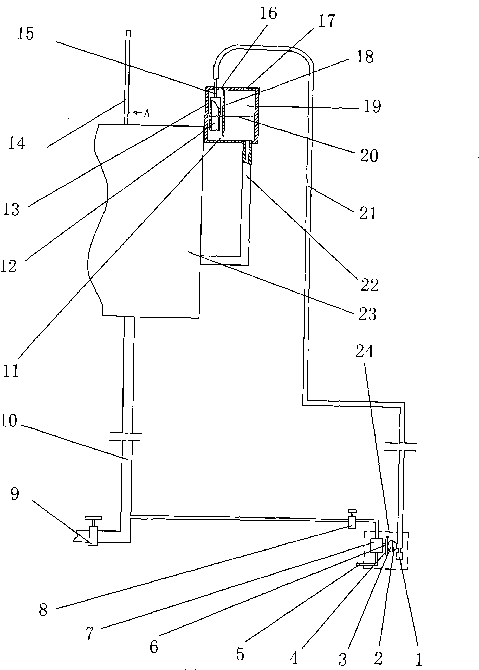
[0007] figure 1 Among them, 1 is the hydrophobic screw cap, 2 is the seat of the air bag, 3 is the membrane of the air bag, 4 is the pressure piece, 5 is the inlet pipe, 6 is the pressure rod on the small flow micro-valve, 7 is the small-flow micro-valve, 8 is the water outlet valve, 9 is the water valve, 10 is the water pipe, 11 is the bottom seam, 12 is the air pressure pipe, 13 is the high liquid level control box, 14 is the air discharge pipe, 15 is the air pressure connecting pipe, 16 is the left ventricle Air hole, 17 is the vent hole in the right chamber, 18 is the steam partition, 19 is the overflow tank, 20 is the compressed air water level line, 21 is the air pressure transmission pipe, 22 is the water guide pipe, 23 is the water tank, 24 is the water tank inlet pipe, 25 refers to The dotted line in represents the pneumatic valve device composed of the above-mentioned 1, 2, 3, 4, 5, 6, and 7 components. figure 1 The middle deflation pipe 14 and the water guide pipe ...


PUM


Abstract

The invention discloses a solar water tank water-saving type liquid level controlling method. A solar water tank is included. A high liquid level control box is arranged on the side of the water tank. An air pressing pipe is connected to one side of the high liquid level control box. A water guide pipe guided from the water tank is communicated with the lower bottom of the other side of the high liquid level control box. An air release pipe on the solar water tank and the high liquid level control box form the two ends of a communicating vessel. The water level of the high liquid level control box rises to enable pressure generated in the air pressing pipe to be transmitted into a pneumatic valve device in a user home and enable an air bag to be inflated to generate swelling force. The swelling force pushes a small-flow inching valve press rod, so that a normally-closed water valve is closed. Thus, an air pressure transmission pipe can close a valve automatically, and the mode that a valve is closed after a user observes water flow in a water pipe is replaced, so that the user is free from worry, and cold water loss is prevented. Moreover, not only the air pressing pipe capable of providing working pressure for the pneumatic valve device but also an overflow groove capable of absorbing thermal expansion water in the solar water tank are arranged in the high liquid level control box, so that the size of the water tank is fully utilized, and hot water cannot be wasted for overflowing.

Description

technical field [0001] The invention belongs to the field of automatic control of the liquid level of a solar water tank, in particular to a water-saving liquid level control method of a solar water tank. Background technique [0002] In today's solar water heaters, when the cold water is fed, the liquid level control is generally controlled by people. The human control is mainly based on an overflow pipe on the water tank of the solar water heater. One end of the overflow pipe is connected to the top of the water tank, and the other end is always connected to the user. In the pool at home, when the solar water tank on the roof overflows, the overflow flows to the pool of the user's home through the overflow pipe. When people see the overflow in the overflow pipe, they immediately close the water inlet valve, and the water tank stops water intake. Because the overflow pipe is very long, the water in the pipe is usually put into the pool to flow away in vain, and someone has ...

Claims


Application Information

Patent Timeline
IPC IPC(8): F24J2/40F24J2/46
CPCY02E10/40
Inventor 陈宜中陈展天
Owner 海门市创豪工业设计有限公司
Why Eureka
Try Eureka