
Method for determining brake transient load position of crane (brake slip amount detection)

A determination method and crane technology, applied in the direction of measuring devices, load hanging components, instruments, etc., can solve the problems of large random time delay, large measurement error of instantaneous load position during braking, etc., to improve consistency and realize automatic high precision measured effect

Inactive Publication Date: 2014-04-09
SOUTHEAST UNIV +1
View PDF6 Cites 5 Cited by
  • Summary
  • Abstract
  • Description
  • Claims
  • Application Information

AI Technical Summary

Problems solved by technology

[0009] The purpose of the present invention is to provide a method for determining the braking instantaneous load position based on the braking signal sensitive circuit and the ultrasonic distance measuring sensor for the detection of the braking sliding amount of a crane, so as to solve the problems existing in the traditional crane braking sliding amount detection method The timing of the braking instantaneous moment has a large random delay, and the problem of the large measurement error of the braking instantaneous load position

Method used


Image

  • Method for determining brake transient load position of crane (brake slip amount detection)
  • Method for determining brake transient load position of crane (brake slip amount detection)
  • Method for determining brake transient load position of crane (brake slip amount detection)

Examples


Embodiment Construction

[0021] Below in conjunction with accompanying drawing, technical scheme of the present invention is described in further detail:

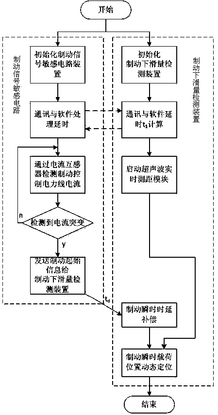
[0022] Examples of the present invention are figure 1 , figure 2 , image 3 , Figure 4 and Figure 5 As shown, it is a method for determining the instantaneous load position of the crane (brake slip detection). First, the brake signal sensitive circuit 2 monitors the current of the power cable of the crane brake through the current transformer connected to it, and identifies the brake signal. The brake signal is sent to the braking slip detection device 3 through short-distance wireless communication, and the braking slip detection device 3 obtains the instantaneous braking moment of the crane through the precise timing method of the braking instant; The dynamic positioning algorithm of the position accurately measures the braking instantaneous position of the load during the movement.

[0023] In the system initialization stage, the brakin...


PUM


Abstract

The invention discloses a method for determining a brake transient load position of a crane (brake slip amount detection). The method is characterized by comprising the following steps of receiving a moment of brake information transmitted by a brake signal sensitive circuit through a short-distance wireless communication way by a brake slip-amount detection device, subtracting the communication transmission and software processing delay time and the brake signal detection circuit hardware delay time to obtain a real brake transient moment of the crane, and accurately measuring a brake transient position of a load in the movement process through a dynamic positioning algorithm of the brake transient load position. By adopting the method, the problem of the traditional crane brake slip-amount detection method that the timing of the real brake transient moment is severely delayed can be solved, and the brake slip-amount detection consistency can be improved; the problem that the error in measuring the brake transient down load position of the crane is large in the dynamic measurement process based on an ultrasonic ranging sensor can be solved, and the automatic high-precision measurement of the brake slip-amount detection brake transient down load position can be realized.

Description

technical field [0001] The invention relates to a method for determining the braking instantaneous load position of a crane (detection of braking slippage), in particular to a method for measuring and determining the instantaneous braking load position of a crane (detection of braking slippage) based on ultrasonic ranging technology. Background technique [0002] Crane braking slide detection is to issue a braking command to the rated load suspended on the crane and drop at a constant speed, and measure the distance that the load slides due to its own weight after the crane brakes. Record braking instantaneous load height , the final height of the load after braking , then the braking slip is . Excessive braking slide will directly affect the safety of on-site staff and equipment. Therefore, the braking slide is an important indicator to measure the performance of the crane, and it is also an important content of the mandatory inspection of the performance of the lifti...

Claims


Application Information

Patent Timeline
Patent Type & Authority Applications(China)
IPC IPC(8): B66C13/16B66C13/18G01B21/02
Inventor 王晓俊王祎季亮袁易之李超周杏鹏
Owner SOUTHEAST UNIV
Learn More