
A kind of ceramic spring forming device and preparation method of ceramic spring

A spring forming and forming device technology, which is applied in the field of ceramic springs, can solve problems such as material defects and irregular shapes, and achieve the effects of reducing reliability in use, fewer defects, and improving dimensional accuracy

Inactive Publication Date: 2015-11-11
XIAMEN UNIV
View PDF11 Cites 0 Cited by
  • Summary
  • Abstract
  • Description
  • Claims
  • Application Information

AI Technical Summary

Problems solved by technology

[0009] The purpose of the present invention is to provide a ceramic spring forming device and a preparation method for ceramic springs in order to solve the problems of complex-shaped blank forming in the ceramic spring manufacturing process and material defects and irregular shapes in the forming process.

Method used

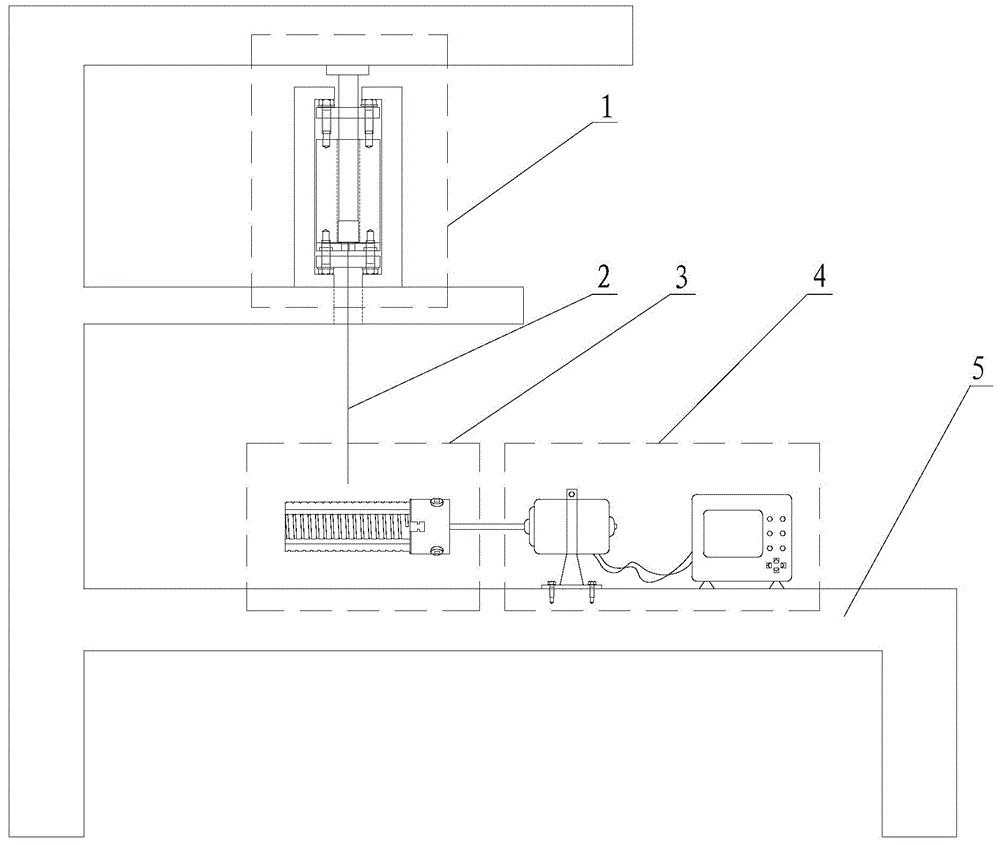

Image

  • A kind of ceramic spring forming device and preparation method of ceramic spring
  • A kind of ceramic spring forming device and preparation method of ceramic spring
  • A kind of ceramic spring forming device and preparation method of ceramic spring

Examples


Embodiment 1

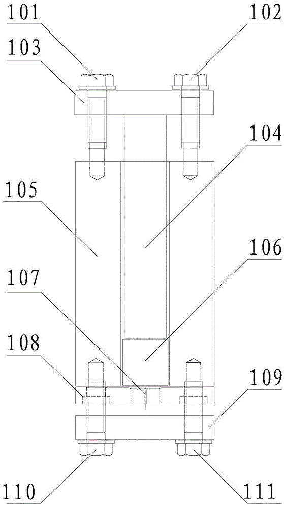
[0058] 1) To obtain continuous polycarbosilane filaments: take 50 g of solid polycarbosilane, and then put it into the barrel 105 of the melt spinning forming device. After assembly, put the melt spinning forming device 1 into the vacuum furnace, and set the temperature rise Rise from room temperature to 200°C in 100 minutes, then rise from 200 to 300°C in 100 minutes, keep warm for 3 hours, take out the melt spinning molding device after natural furnace cooling, put it into a small melt spinning machine immediately, and set the spinning temperature to 280°C , and then spray polycarbosilane filaments 2.

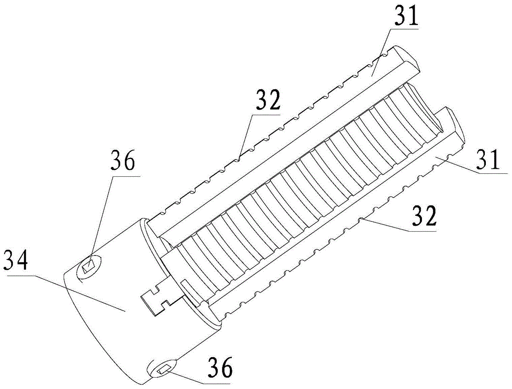
[0059] 2) Polycarbosilane spring winding molding: use a voltaic wrench to rotate the small bevel gear 36, adjust the outer diameter of the cylinder formed by the three arc-shaped clamping plates 31 to 20mm, and install it on the motor 41 whose speed is set at 20 rpm On, use tweezers to pull the continuous polycarbosilane filament 2 to the arc groove 32 of the arc-shaped clamp...

Embodiment 2

[0065] 1) To obtain continuous polyaluminocarbosilane filaments: take 50 g of solid polyaluminocarbosilane, and then put it into the barrel 105 of the melt-spinning forming device. After assembly, put the melt-spinning forming device 1 into the vacuum furnace, and set The temperature rise program takes 100 minutes to rise from room temperature to 200°C, and then takes 100 minutes to rise from 200 to 340°C, keep warm for 3 hours, take out the melt spinning forming device 1 after natural furnace cooling, immediately put it into a small melt spinning machine, and set the spinning temperature to 320°C, and then spray polyaluminocarbosilane filaments 2.

[0066] 2) Polyaluminocarbosilane spring winding molding: use a voltaic wrench to rotate the small bevel gear 36, adjust the outer diameter of the cylinder formed by the three arc-shaped clamping plates 31 to 20mm, and install it on the motor 41 whose speed is set at 20r / min First, use tweezers to pull the continuous polyaluminocar...


PUM

PropertyMeasurementUnit
diameteraaaaaaaaaa
lengthaaaaaaaaaa
strengthaaaaaaaaaa

Abstract

The invention provides a forming device and a manufacturing method of a ceramic spring, and relates to the ceramic spring. The forming device of the ceramic spring is provided with a melt spinning forming device, a spring winding forming device, a driving mechanism and a support table. The melt spinning forming device is provided with an upper sealing cover, a mandril, a charging basket, a spinneret plate and a lower sealing cover; the spring winding forming device comprises a chuck body, three arc-shaped clamp plates and a chuck driving mechanism, and the chuck driving mechanism is provided with a big bevel gear and three bevel pinions; the driving mechanism is provided with an electric motor and a controller. The method includes the steps of (1) obtaining a continuous polycarbosilane filament; (2) forming a polycarbosilane spring in a wound mode; (3) carrying out oxidative crosslinking processing; (4) carrying out high-temperature presintering; (5) taking out the ceramic spring; (6) carrying out high-temperature final sintering to obtain a ceramic spring finished product. Thus, the continuous polycarbosilane filament which is small in defect, uniform, compact and controllable in thickness can be obtained, the use reliability declining problem of the ceramic spring due to material defects is effectively solved, and the process is simple and easy to achieve.

Description

technical field [0001] The invention relates to a ceramic spring, in particular to a ceramic spring forming device and a preparation method of the ceramic spring. Background technique [0002] As one of the most commonly used mechanical basic parts, springs are used to control the movement of parts, alleviate shocks or vibrations, store energy, measure force, etc., and are widely used in various mechanical equipment. At present, the main materials for making springs are high-quality carbon steel, alloy steel, non-ferrous metal alloys, etc., but with the development of science and technology, many high-tech fields have increasingly stringent requirements for the performance of springs, and metal springs can no longer meet the needs of new energy sources. , national defense, chemical industry, aerospace and other fields of use requirements. In many device designs, spring parts are required to be used stably in extreme environments such as high temperature, strong acid, strong...

Claims


Application Information

Patent Timeline
Patent Type & Authority Patents(China)
IPC IPC(8): B28B1/24C04B35/565C04B35/622
CPCB28B1/24C04B35/565C04B35/622
Inventor 姚荣迁符长平杨丽观冯祖德
Owner XIAMEN UNIV
Learn More