Novel constant force polishing and waxing device

A constant force and new technology, applied in the field of polishing machinery, can solve the problems of non-compact structure of cloth throwing wheel, uneven waxing, complex structure, etc., and achieve the effect of compact structure, uniform waxing and improved working environment

Inactive Publication Date: 2014-04-02
SOUTH CHINA UNIV OF TECH
View PDF5 Cites 17 Cited by
  • Summary
  • Abstract
  • Description
  • Claims
  • Application Information

AI Technical Summary

Problems solved by technology

However, the existing cloth throwing wheels on the market are not compact in structure, uneven in waxing and complex in structure

Method used


Image

  • Novel constant force polishing and waxing device
  • Novel constant force polishing and waxing device
  • Novel constant force polishing and waxing device

Examples


Embodiment 1

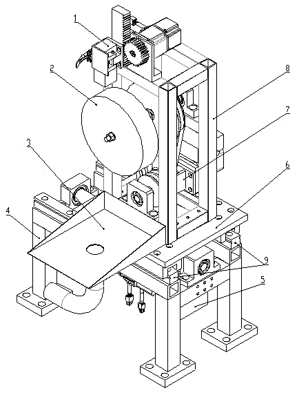
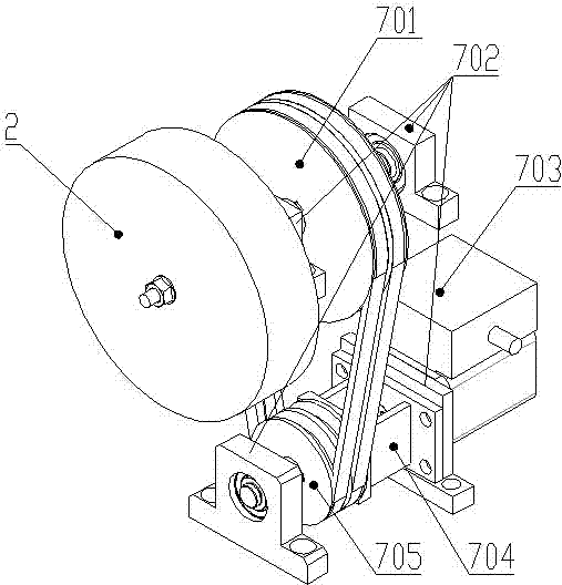
[0026] like Figure 1 to Figure 5 As shown, a new type of constant force polishing and waxing device includes a first frame 4, the top of the first frame 4 is provided with a support plate 6 that can move back and forth along the guide rail, and the upper surface of the support plate 6 is provided with There is a second support 8, which also includes a waxing mechanism arranged on the upper end of the second support 8, a mobile module 5 arranged on the first frame 4, a polishing module 7 arranged on the support plate 6 and positioned below the waxing mechanism and The cloth throwing wheel 2 drivingly connected with the polishing module 7 , and the dust collection module 3 arranged on the support plate 6 and the second support 8 and located below the cloth throwing wheel 2 .

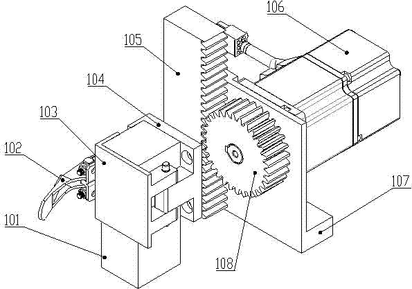
[0027] like figure 2 As shown, the waxing mechanism includes a waxing module 1, the fixed plate 107 of the waxing module 1 is fixed on the second frame 8, and the wax strip 101 passes through the hinged...

Embodiment 2

[0033] like Image 6 and Figure 7 As shown, the difference between this embodiment and Embodiment 1 is that the waxing mechanism includes a wax spraying module 10, the cylinder 1002 of the wax spraying module 10 is fixed on the second frame 8 through the cylinder fixing plate 1001, and the wax bottle 1011 is fixed on the second frame 8 through the first support seat 1008 of the wax bottle and the second support seat 1010 of the wax bottle, the moving plate 1004 is fixed on the slide block 1005, and the cylinder 1002 drives the moving plate 1004 along with the The slide block 1005 slides along the guide rail 1006 fixed on the second frame 8, thereby driving the push plate 1007 fixed on the moving plate 1004 to move along the direction of the guide rail 1006, and then presses the nozzle of the wax bottle 1011 to spray the liquid wax onto the cloth. Above the throwing wheel 2, a rotation stopper pin 1009 to prevent the wax bottle 1011 from rotating is set on the first support s...


PUM


Abstract

The invention relates to a novel constant force polishing and waxing device which comprises a first frame. A support plate capable of moving back and forth along a guide rail is arranged at the top end of the first frame, and a second support is arranged on the upper surface of the support plate. The device further comprises a waxing mechanism arranged at the upper end of the second support, a moving module arranged on the first frame, a polishing module arranged on the support plate and located under the waving mechanism, a cloth polishing wheel connected with the polishing module in a driving mode and a dust collection module arranged on the support plate and the second support and located under the cloth polishing wheel. The polishing and waxing device adopts a gear rack gradual wax rod feeding device, and enables the cloth polishing wheel to be even in waxing. For liquid wax which becomes common gradually at present, a four-rod wax spraying device is adopted to enable the cloth polishing wheel to be even in waxing. A quick clamp device is adopted to achieve quick replacement of wax rods and improve working efficiency. By means of a dust collection device, working environment is improved. A servo motor adopts a built-in structure, so that the polishing and waxing device is compact in structure and saves space.

Description

[0001] technical field [0002] The invention relates to the field of polishing machinery. In particular, it relates to a novel constant force polishing and waxing device. Background technique [0003] The constant force polishing and waxing device is an automatic equipment that uses a high-speed rotating polishing wheel to press against the workpiece, so that the abrasive can roll and micro-cut the surface of the workpiece to obtain a bright processed surface. It has constant polishing force and waxing. Due to the advantages of uniformity and compact structure, due to its high degree of automation and low cost, it is more and more used in the field of micro-polishing of stainless steel, brass, aluminum, plastics, etc. The quality of the product after polishing directly affects the use effect and life of the product. [0004] At present, the research on the technology and equipment of the cloth throwing machine at home and abroad is nearly mature. However, the existing cl...

Claims


Application Information

Patent Timeline
Patent Type & Authority Applications(China)
IPC IPC(8): B24B29/00B24B55/06
CPCB24B39/00B24B55/06
Inventor 汪芳胜岳伟玲王枫红陈炽坤朱其锴
Owner SOUTH CHINA UNIV OF TECH
Why Eureka
Try Eureka