
Extrusion press

A technology for extruders and extrusion barrels, applied in the field of extrusion machines that seek multi-function and shorten idle time, can solve the problems of increasing the stripping force of extrusion barrels, consuming useless energy, and poor energy efficiency. Achieving increased peeling force, easy design, and improved energy efficiency

Active Publication Date: 2014-03-26
UBE MASCH CORP LTD
View PDF7 Cites 16 Cited by
  • Summary
  • Abstract
  • Description
  • Claims
  • Application Information

AI Technical Summary

Problems solved by technology

[0010] However, in the above-mentioned conventional extrusion machine, since the extrusion cylinder 16 is made into a structure installed on the main cylinder shell 4 in this way, there is no interference with other parts and other mechanisms in the extrusion machine. Considering the relationship between the existence and non-existence of the extrusion cylinder, increasing the peeling force of the extrusion cylinder will bring about difficulties in the design strength and structure.
[0011] In addition, since the above-mentioned operation is performed by the above-mentioned extrusion cylinder 16, there is a problem that a large amount of pressure oil is supplied, useless energy is consumed, and energy efficiency is poor.

Method used


Image

  • Extrusion press
  • Extrusion press

Examples


Embodiment Construction

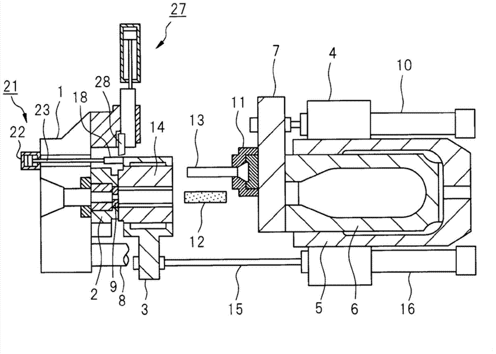
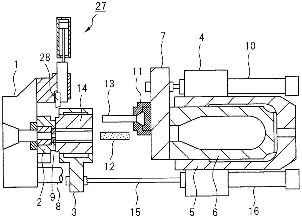
[0027] Below, according to figure 1 The present invention will be described in detail. figure 1 It shows an embodiment of the extrusion machine of the present invention, 1 is an end table, 2 is a die slide device equipped with a die 9 for product extrusion, and 3 is an extrusion for storing an extrusion material (billet) 12 The cylinder 14 holds the extrusion cylinder holder, 4 is the main cylinder shell, 5 is the main cylinder, 6 is the main piston, 7 is the main crosshead integrally installed at the front end of the main piston 6, and 10 is the main crosshead for the main cylinder. The movement of 13, the side cylinder that is located on the left and right horizontal outer parts of master cylinder 5.

[0028] On the front end portion of the main crosshead 7 , a squeeze bar slider 11 is slidably attached in a vertical or horizontal direction perpendicular to an axis direction which is the forward and backward travel direction of the main crosshead 7 . An extruding rod 13 ...


PUM


Abstract

Provided is a short stroke type extrusion press which is capable of increasing a container strip force, improving energy efficiency, and saving space by reducing apparatus length. A main cylinder housing (4) of the extrusion press comprises a transfer medium (10) which advances or retreats an extrusion stem (13) in an extrusion axis direction, and a transfer medium (16) which advances or retreats a container (14) in the extrusion axis direction. A container pushing medium (21) is disposed at an end platen (1) disposed opposite the main cylinder housing (4) and makes it possible for at least four different transfer motions to be carried out independently or in collaboration with the container transfer medium in the direction in which the container (14) separates from a die (9).

Description

technical field [0001] Cross-references related to related applications [0002] The present invention proposes a patent claim based on the priority of patent application 2011-173675 filed on August 9, 2011, and these contents are incorporated as references in this specification, and continue in this application. [0003] The present invention relates to an extruder used for metal extrusion molding such as aluminum alloys, particularly to an extruder of a short-stroke type with shortened machine length and space saving, and to an extruder that achieves multifunctionality and shortens idle time . Background technique [0004] Generally, in the case of extruding extruded materials (billets) made of metal materials such as aluminum or its alloy materials by an extruder, an extruding rod is installed at the front end of the main piston driven by a hydraulic cylinder. In the state where the extrusion cylinder is pressed against the die, the extrusion material (billet) is stored...

Claims


Application Information

Patent Timeline
Patent Type & Authority Applications(China)
IPC IPC(8): B21C27/00B21C35/04
CPCB21C33/00B21C35/04B21C23/211B21C27/00B21C23/215
Inventor 山本武治中野幸次
Owner UBE MASCH CORP LTD
Learn More