Power supply device and lighting device

A power supply device and circuit technology, which is applied to lighting devices, electric light sources, electroluminescent light sources, etc., can solve the problems of increased detection error and inability to adjust light smoothly, and achieve stable light adjustment

Active Publication Date: 2014-03-26
TOSHIBA LIGHTING & TECH CORP
View PDF4 Cites 0 Cited by
  • Summary
  • Abstract
  • Description
  • Claims
  • Application Information

AI Technical Summary

Problems solved by technology

[0005] However, in the case of deep dimming close to extinction, the current value becomes small and the detection error increases
In addition, since the characteristics of light-emitting diodes fluctuate due to manufacturing fluctuations or temperature dependence, etc., it may not be possible to perform smooth dimming from full lighting to extinguishing through deep dimming.

Method used


Image

  • Power supply device and lighting device
  • Power supply device and lighting device
  • Power supply device and lighting device

Examples


no. 1 approach )

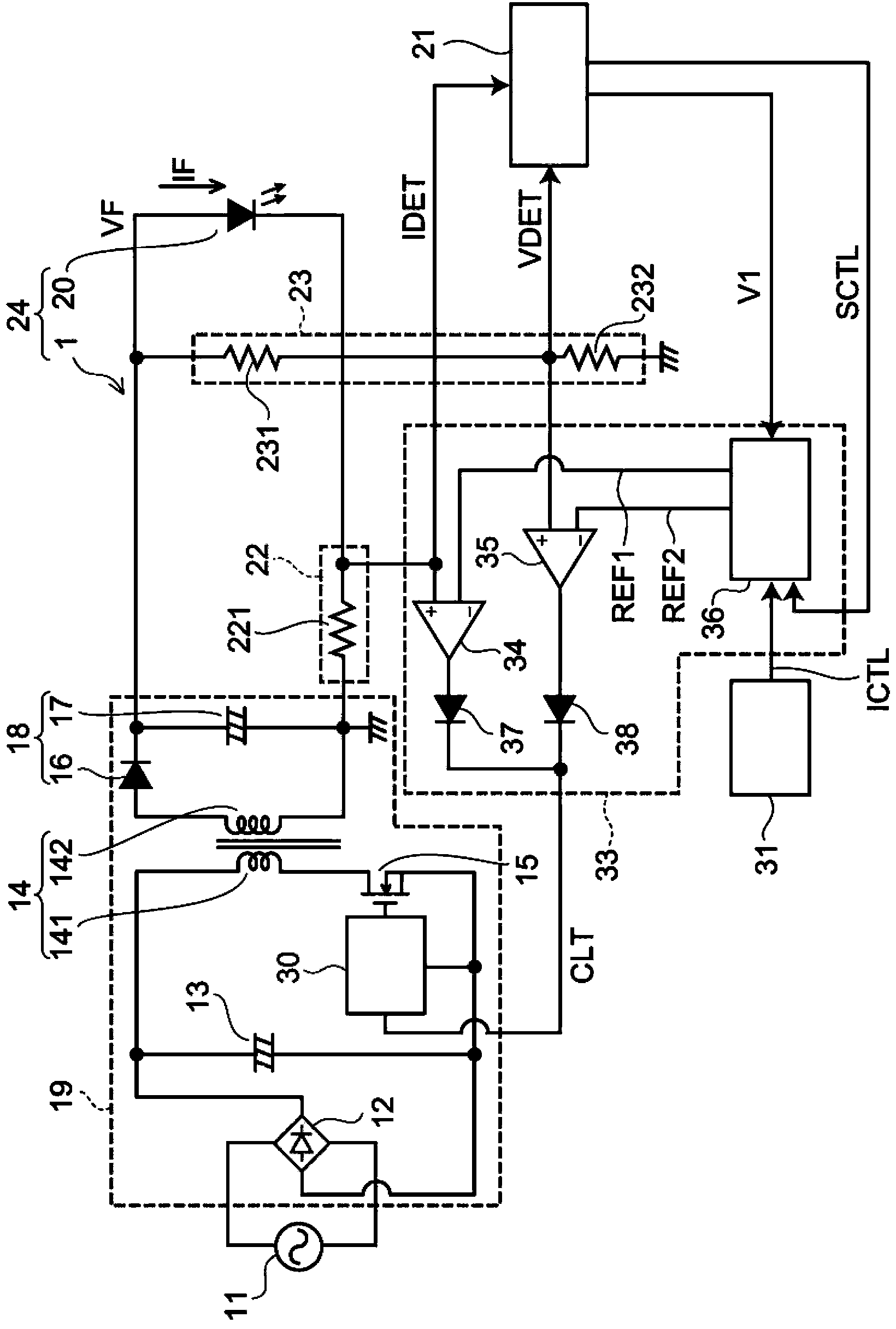
[0020] figure 1 It is a circuit diagram illustrating an illumination device including the power supply device of the first embodiment.

[0021] The lighting device 24 of the first embodiment includes the light emitting element 20 and the power supply device 1 . The power supply device 1 includes a DC power supply circuit 19 , a first circuit 21 , a current detection circuit 22 , a voltage detection circuit 23 , and a control circuit 33 . The power supply device 1 is a power supply device that controls an output current IF and an output voltage VF supplied to the light emitting element 20 in accordance with a control signal CTL to adjust light.

[0022] The DC power supply circuit 19 has a rectification circuit 12 , a capacitor 13 , a transformer 14 , a switching element 15 , a rectification smoothing circuit 18 , and a drive circuit 30 . The DC power supply circuit 19 converts the AC voltage supplied from the AC power supply 11 into a DC voltage. It should be noted that the...

no. 2 approach )

[0060] Figure 4 It is a circuit diagram illustrating the reference signal generation circuit of the second embodiment.

[0061] The power supply device of the second embodiment is configured by replacing the reference signal generating circuit 36 ​​of the first embodiment with a reference signal generating circuit 36a. The configuration other than the reference signal generating circuit 36 ​​a of the second embodiment is the same as that of the first embodiment.

[0062] The reference signal generation circuit 36 ​​a has: a first signal generation circuit 361 that generates a first reference signal REF1 ; a second signal generation circuit 362 that generates a second reference signal REF2 ; and diodes 39 , 40 .

[0063] The first reference signal REF1 and the second reference signal REF2 are set or corrected by the first circuit 21 as in the case of the first embodiment. It should be noted that, in Figure 4 Although the configuration in which the first reference signal RE...


PUM


Abstract

The present invention provides a power supply device and a lighting device, which can dim a light-emitting element stably. The power supply device includes a control circuit and a detection circuit.The control circuit switches between a current control mode and a voltage control mode according to an inputted dimming signal and thus dims the light-emitting element. In the current control mode the control circuit controls an output current supplied to the light-emitting element to a target current, and in the voltage control mode the control circuit controls an output voltage supplied to the light-emitting element to a target voltage. The detection circuit detects the output current and the output voltage, and the control circuit sets the target voltage switched between the current control mode and the voltage control mode as a first voltage.

Description

technical field [0001] The invention relates to a power supply device and a lighting device. Background technique [0002] In recent years, in lighting devices, the replacement of lighting sources from incandescent light bulbs or fluorescent lamps to energy-saving and long-life light sources such as light-emitting diodes (LEDs) has progressed. Moreover, new lighting sources such as EL (Electro-Luminescence) or organic light-emitting diode (Organic light-emitting diode: OLED) have also been developed. The light output of these illumination light sources depends on the value of the current flowing therethrough, and therefore a lighting device capable of controlling the value of the supplied current is required in order to turn on and adjust the light of the illumination light source. For example, a power supply device that lights up a light emitting diode needs to be controlled over a wide range from the maximum current that completely lights up the light emitting diode to ze...

Claims


Application Information

Patent Timeline
Patent Type & Authority Applications(China)
IPC IPC(8): H05B37/02H05B44/00
CPCH05B33/0851H05B33/0815H05B33/0854H05B45/10Y02B20/30H05B45/18H05B45/382
Inventor 高桥浩司中岛启道坂井健治工藤启之大武宽和寺坂博志甲佐清辉斋藤阳介熊谷昌俊松本晋一郎小塚日出夫佐藤和彦小西达也
Owner TOSHIBA LIGHTING & TECH CORP
Why Eureka
Try Eureka