
Phase locked loop circuit and method of generating clock signals using the phase locked loop

A reference clock signal, phase-locked loop technology, applied in the direction of electrical components, automatic power control, etc., can solve problems such as complex analog circuits

Inactive Publication Date: 2014-03-26
GLOBALFOUNDRIES INC
View PDF9 Cites 17 Cited by
  • Summary
  • Abstract
  • Description
  • Claims
  • Application Information

AI Technical Summary

Problems solved by technology

Various circuit architectures and methods for implementing an analog proportional control path are known in the art, but these techniques have the disadvantage of requiring a large amount of complex analog circuitry

Method used


Image

  • Phase locked loop circuit and method of generating clock signals using the phase locked loop
  • Phase locked loop circuit and method of generating clock signals using the phase locked loop
  • Phase locked loop circuit and method of generating clock signals using the phase locked loop

Examples


Embodiment Construction

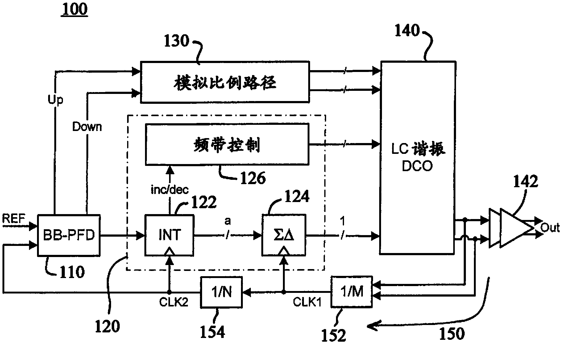
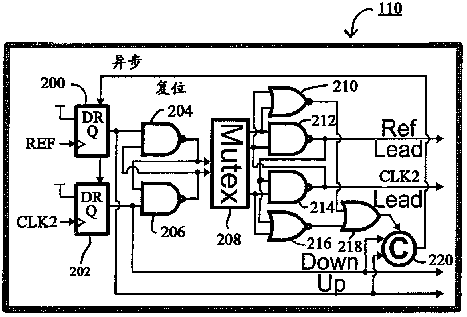
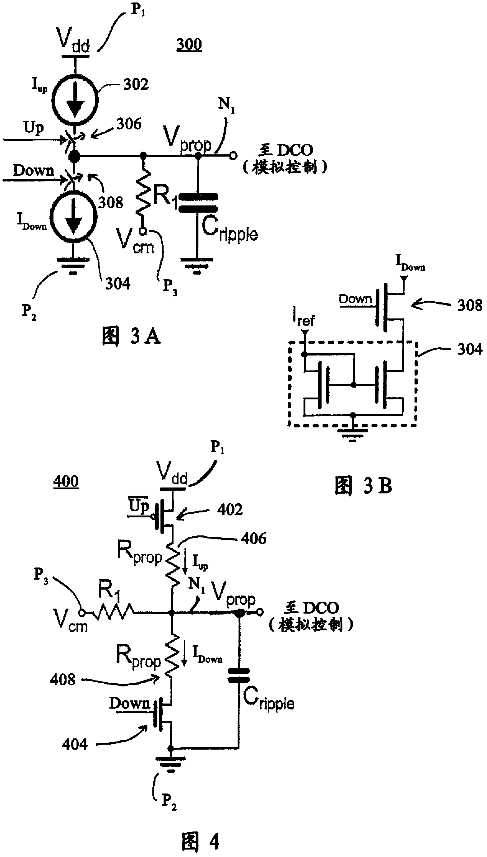
[0021] Exemplary embodiments will now be discussed in further detail for phase locked loop (PLL) architectures, such as hybrid PLL architectures with a digital integral path and an analog proportional path. figure 1 is a block diagram of a hybrid PLL circuit according to one embodiment of the present invention. Specifically, figure 1 The architecture of hybrid PLL circuit 100 is shown, which includes phase-frequency detector 110 , digital integral control path 120 , analog proportional control path 130 , digitally controlled oscillator 140 (DCO), output buffer 142 and feedback path 150 . Digital integration control path 120 includes digital integration circuit 122 , sigma-delta (sigma-delta) circuit 124 , and band control circuit 126 . The feedback path 150 includes a first clock divider circuit 152 that generates a first clock signal ( CLK1 ), and a second clock divider circuit 154 that generates a second clock signal ( CLK2 ). The first clock frequency dividing circuit 152...


PUM


Abstract

The invention refers to a phase locked loop circuit and a method of generating clock signals using the phase locked loop. Phase locked loop (PLL) architectures are provided such as hybrid PLL architectures having separate digital integrating control paths and analog proportional control paths. An analog proportional control path can be implemented with a charge pump circuit that includes resistors in series with CMOS switches to generate control currents (e.g., Up / Down control currents) which are used to adjust a control voltage applied to a digitally controlled oscillator. A digital integrating control path can be implemented with a series of sigma-delta modulators that operate at different frequencies to convert higher bit data signals to lower bit data signals along the digital integrating control path. A single phase frequency detector may be implemented to generate control signals that separately control the analog proportional and digital integrating control paths.

Description

technical field [0001] The field generally relates to phase locked loop (PLL) architectures, such as hybrid PLL architectures having a digital integral path and an analog proportional path. Background technique [0002] In general, a PLL is a circuit designed to minimize the frequency and / or phase difference between two signals. PLL circuits are used in a wide variety of applications where two signals that have a known relationship to each other must be involved. For example, when transmitting information from a sending device to a receiving device, the receiving device must have a local clock that is synchronized with the clock of the sending device so that the information can be transmitted reliably. [0003] PLL circuits can be implemented using various types of known architectures, where the forward control path of the PLL circuit includes separate proportional and integral control paths. In an all-digital implementation, both the proportional and integral control path...

Claims


Application Information

Patent Timeline
Patent Type & Authority Applications(China)
IPC IPC(8): H03L7/085H03L7/099
CPCH03L7/087H03L7/093H03L7/089H03L7/1072
Inventor H·A·安斯潘M·A·费里斯D·J·弗里德曼A·V·雷利亚科夫J·A·蒂尔诺
Owner GLOBALFOUNDRIES INC
Learn More