Miniature dynamic osmotic water pressure sensor

A technology of pressure sensor and water penetration, applied in the direction of measuring fluid pressure, measuring fluid pressure through electromagnetic components, instruments, etc., can solve the problems of affecting the measurement accuracy of the sensor, corroding the sensing surface of the stainless steel diaphragm, and the measurement cannot be carried out, so as to improve the effective Service life and long-term stability, improvement of dynamic frequency response and measurement accuracy, and prevention of soil penetration and water corrosion

Active Publication Date: 2016-06-01
昆山昆博智能感知产业技术研究院有限公司
View PDF7 Cites 0 Cited by
  • Summary
  • Abstract
  • Description
  • Claims
  • Application Information

AI Technical Summary

Problems solved by technology

The silicon piezoresistive sensor is a silicon microchip structure, which cannot directly contact the corrosive mud and seepage water in the soil, that is, it cannot be used as a direct sensing surface. It must be packaged in a stainless steel shell and use a stainless steel diaphragm as the sensing surface. , the inside of the stainless steel shell is filled with silicone oil as the medium for transmitting pressure, so the high-frequency dynamic frequency response signal is not easy to obtain during use
Due to the elastic force of the stainless steel diaphragm between the permeated water and the pressure sensitive component, it affects the measurement accuracy of the permeated water pressure sensor
In addition, the seepage water in the soil contains a small amount of mud, and it is easy to block and corrode the sensing surface of the stainless steel diaphragm after long-term use, so that the measurement accuracy of the sensor is affected, and the sensor is more likely to be damaged, making the measurement impossible

Method used


Image

  • Miniature dynamic osmotic water pressure sensor
  • Miniature dynamic osmotic water pressure sensor

Examples


Embodiment

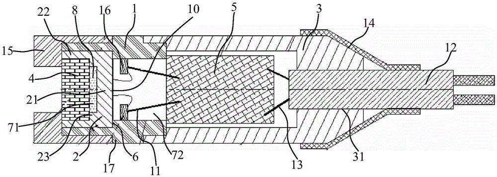
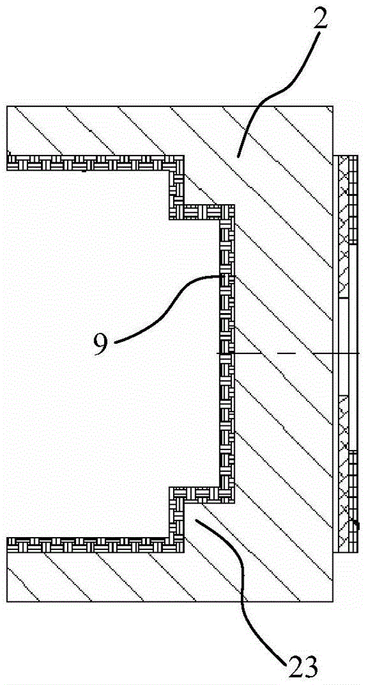
[0018] Embodiment: A miniature dynamic osmotic water pressure sensor, including a housing 1, a cup-shaped base 2 composed of a bottom plate 21 and a side plate 22 fixed to the circumference of the bottom plate 21, a stainless steel back cover 3, a permeable stone layer 4 and signal modulation Amplifying module 5, the middle part of the inner wall of the housing 1 has a stepped annular surface 6, thereby forming a connected pre-chamber 71 and a rear chamber 72, a flange 24 is located in the middle of the outer surface of the housing; the inner wall of the cup-shaped base 2 has steps Surface 23, a permeable stone layer 4 is installed on the step surface 23 of the cup-shaped base 2, thereby forming a permeable water chamber 8 between the permeable stone layer 4 and the bottom of the cup-shaped base 2; The base 2 is embedded in the front chamber 71 and installed on the stepped circular surface 6 of the housing 1; the stainless steel rear cover 3 is installed on one end of the housi...


PUM

PropertyMeasurementUnit
thicknessaaaaaaaaaa
diameteraaaaaaaaaa
diameteraaaaaaaaaa

Abstract

The invention discloses a minitype dynamic infiltration water pressure sensor which comprises a shell, a cup-shaped base, a stainless steel rear cover, a water permeable stone layer and a signal modulation amplification module. A step surface is arranged on the inner wall of the cup-shaped base, and the water permeable stone layer is mounted on the step surface of the cup-shaped base. The cup-shaped base is embedded into a front cavity and is mounted on the step circular ring surface of the shell. The stainless steel rear cover is mounted at the end, placed on a rear cavity, of the shell, and a silicon nitride thin film covers the inner surface of the cup-shaped base. A pressure sensitive assembly is arranged on the surface, opposite to the water permeable stone layer, of the cup-shaped base, a first leading wire is connected between the pressure sensitive assembly and one end of the signal modulation amplification module in a bridging mode, and a signal cable is embedded into a through hole of the stainless steel rear cover and is connected to the other end of the signal modulation amplification module through a second leading wire. By means of the minitype dynamic infiltration water pressure sensor, the dynamic frequency response and the measurement accuracy of the pressure sensor are improved, the measuring range is greatly increased, sensing precision and sensitivity are also improved, and the degree of linearity of signals of the pressure sensor is improved.

Description

technical field [0001] The invention relates to a pressure sensor, in particular to a miniature dynamic osmotic water pressure sensor. Background technique [0002] At present, the mainstream of measuring water pressure sensors is silicon piezoresistive sensors. The main principle is to use the piezoresistive effect of silicon, adopt MEMS technology and integrated circuit technology to set a certain crystal orientation on a silicon chip, and use oxidation, diffusion or ion implantation to a certain position. Doping, photolithography and other processes are used to make strain-sensitive Wheatstone bridges. Its working range is 1KPa~100Mpa. The silicon piezoresistive sensor is a silicon microchip structure, which cannot directly contact the corrosive mud and seepage water in the soil, that is, it cannot be used as a direct sensing surface. It must be packaged in a stainless steel shell and use a stainless steel diaphragm as the sensing surface. , The interior of the stainles...

Claims


Application Information

Patent Timeline
Patent Type & Authority Patents(China)
IPC IPC(8): G01L9/00G01L19/06
Inventor 程新利唐运海沈娇艳王冰秦长发潘涛臧涛成王文襄
Owner 昆山昆博智能感知产业技术研究院有限公司
Why Eureka
Try Eureka