Filter arrangement and method for producing a filter receptacle

A filter assembly, filter technology, applied in chemical instruments and methods, membrane filters, separation methods, etc., can solve problems such as limiting filter housing and assembly geometry and installation orientation

Active Publication Date: 2014-03-26
MANN HUMMEL GMBH
View PDF5 Cites 2 Cited by
  • Summary
  • Abstract
  • Description
  • Claims
  • Application Information

AI Technical Summary

Problems solved by technology

This measure limits the geometry and installation orientation of the corresponding filter housings and assemblies

Method used


Image

  • Filter arrangement and method for producing a filter receptacle
  • Filter arrangement and method for producing a filter receptacle
  • Filter arrangement and method for producing a filter receptacle

Examples


Embodiment Construction

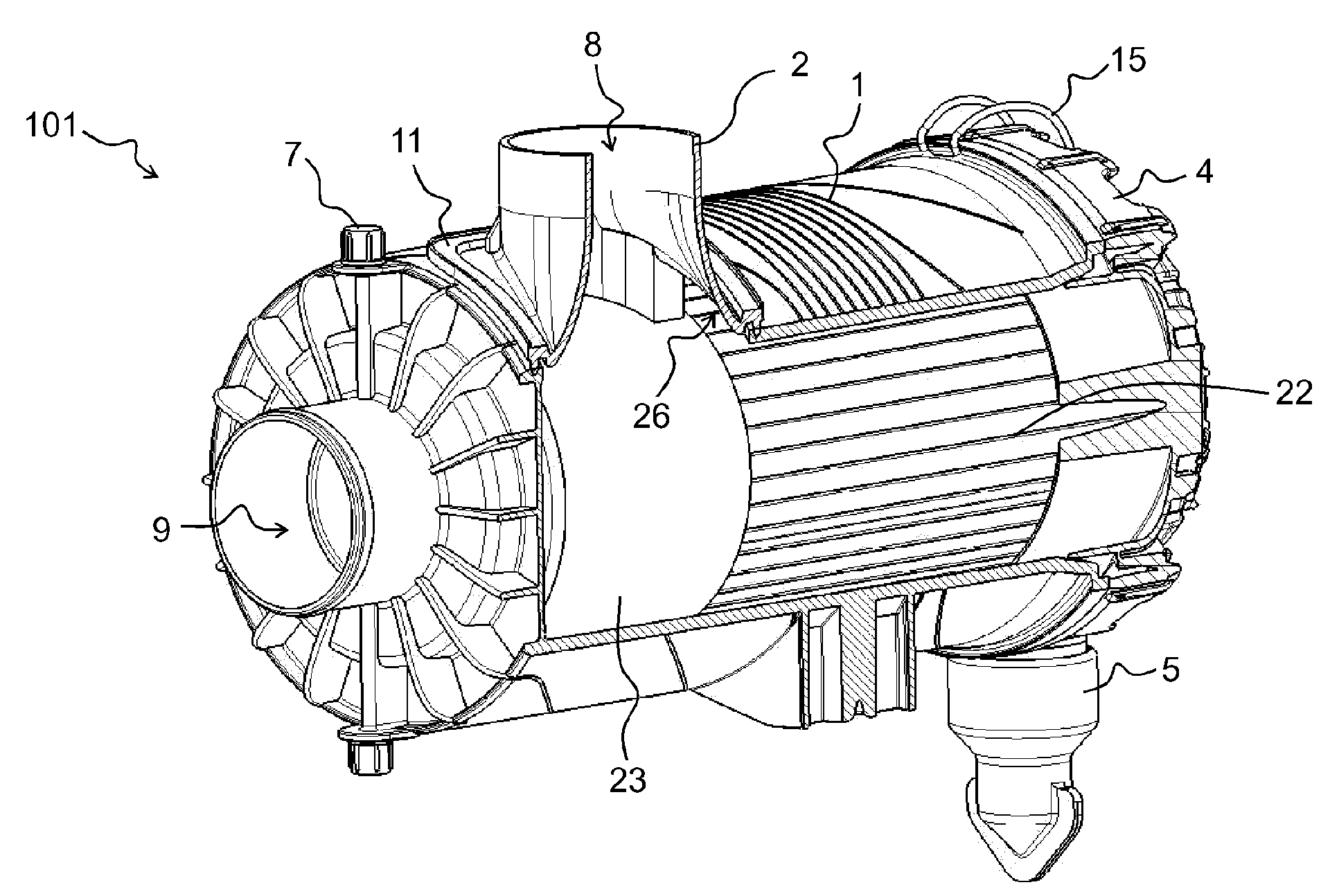
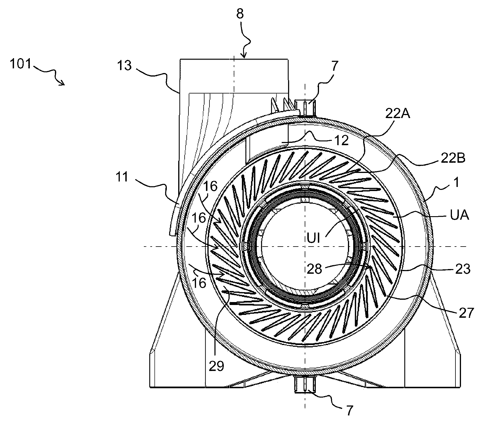
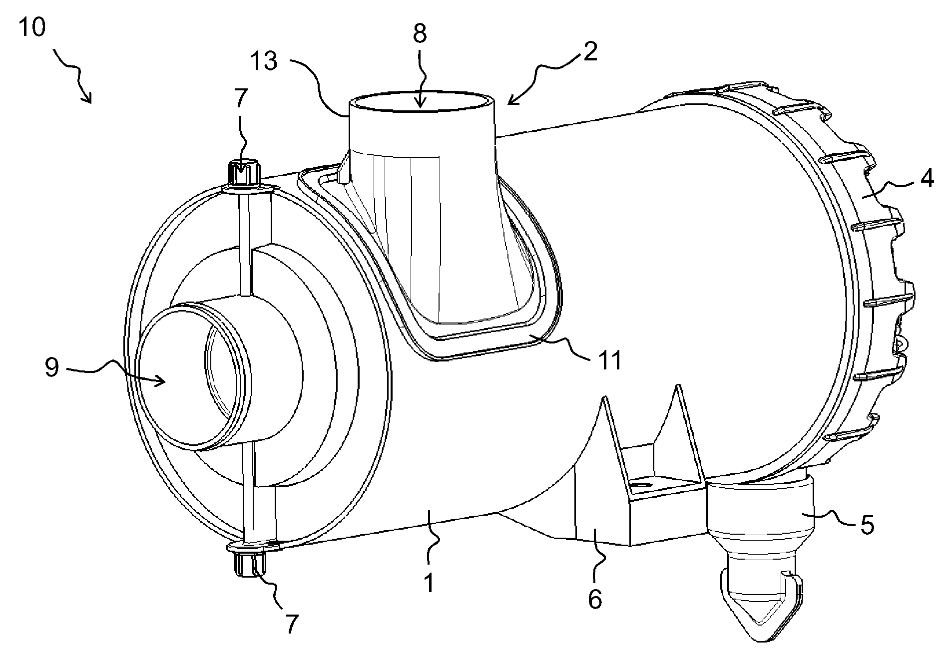
[0032] figure 1 A perspective view of a first embodiment of a filter holder and a filter assembly is shown. exist figure 2 with 3 A perspective illustration of housing parts such as filter housing and filter cover as well as individual inlet connections is shown in . Figure 4 with 5 shows a side view of the filter holder, while Figure 7A partially disassembled perspective illustration of a corresponding filter assembly with the filter elements used is shown.

[0033] first in figure 1 The filter holder 10 is visible in perspective. The filter holder 10 here comprises a substantially cylindrical housing part 1 and a housing cover 4 . The housing part is, for example, a plastic molded part and can be produced by injection molding or other known manufacturing processes. An inflow connection 2 is mounted on the outside of the housing part 1 . The inlet connection 2 comprises a cylindrical section 13 protruding from the housing 1 (which protrudes from the fastening surf...


PUM


Abstract

The invention relates to a filter arrangement and a method for producing a filter receptacle. Concretely, the filter receptacle (10) comprises a housing (1) having an inflow opening (3) and an inflow connection pipe (2) fastened, in particular welded, at the inflow opening (3) and used for coupling to a fluid supply line, wherein the inflow connection pipe (2) has a flow cross-section that varies in a flow direction. In the method for producing the filter receptacle (10), the housing (1) is provided, the inflow opening (3) is mounted in the housing (1), and the inflow connection pipe (2) is fixed at the opening (3).

Description

technical field [0001] The invention relates to a filter assembly and a method for producing a filter holder. A filter element is accommodated in a filter holder or filter housing, forming a filter system or filter assembly overall. Background technique [0002] Circular air filters are known in particular from the automotive field, in which an essentially cylindrical housing accommodates one or more filter elements with filter media. The fluid to be filtered (eg especially contaminated combustion air) flows radially from the inside to the outside through the filter medium or from the outside to the inside and is then supplied to the internal combustion engine. In corresponding filter assemblies it is desirable to keep the flow resistance low. At the same time, the installation space which is at most predetermined by the diameter of the cylindrical housing should be as small as possible. Furthermore, in order to meet the requirements for pollution-free combustion air, mul...

Claims


Application Information

Patent Timeline
Patent Type & Authority Applications(China)
IPC IPC(8): B01D46/24B01D46/42
CPCB01D46/522B01D46/0041B01D46/0046B01D46/2403B01D46/24B01D2265/04B01D46/0002B01D46/2411B01D46/52B01D46/00Y10T156/10
Inventor M.考夫曼K-D.鲁兰
Owner MANN HUMMEL GMBH
Why Eureka
Try Eureka