
CMOS radio frequency receiving front end with wide temperature work gain automatic control function

A gain automatic control, working gain technology, applied in gain control, amplification control, power management and other directions, can solve the problems of change, noise performance deterioration, design difficulty increase, etc., to achieve the effect of simple circuit structure

Active Publication Date: 2014-03-19
CHINA ELECTRONIC TECH GRP CORP NO 38 RES INST
View PDF3 Cites 6 Cited by
  • Summary
  • Abstract
  • Description
  • Claims
  • Application Information

AI Technical Summary

Problems solved by technology

[0013] The purpose of the present invention is to solve the problem that the gain of the radio frequency receiving front-end circuit fluctuates with temperature, and overcome the disadvantages of increased design difficulty, noise performance deterioration, limitations on process selection, and affecting the working bandwidth of the circuit caused by conventional solutions. At this point, it is proposed to use the current bias technology based on the bandgap reference source and the temperature adaptive gain adjustment method to realize the CMOS RF receiving front end with the wide temperature working gain automatic control function of the whole chip in the wide temperature working range

Method used


Image

  • CMOS radio frequency receiving front end with wide temperature work gain automatic control function
  • CMOS radio frequency receiving front end with wide temperature work gain automatic control function
  • CMOS radio frequency receiving front end with wide temperature work gain automatic control function

Examples


Embodiment Construction

[0029] In order to make the object, technical solution and advantages of the present invention clearer, the present invention will be further described in detail below in conjunction with the accompanying drawings and embodiments. It should be understood that the specific embodiments described here are only used to explain the present invention, not to limit the present invention.

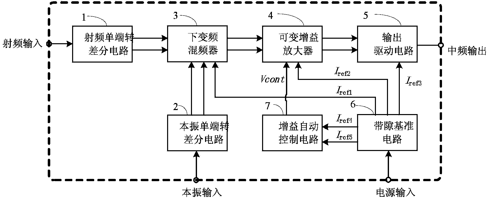
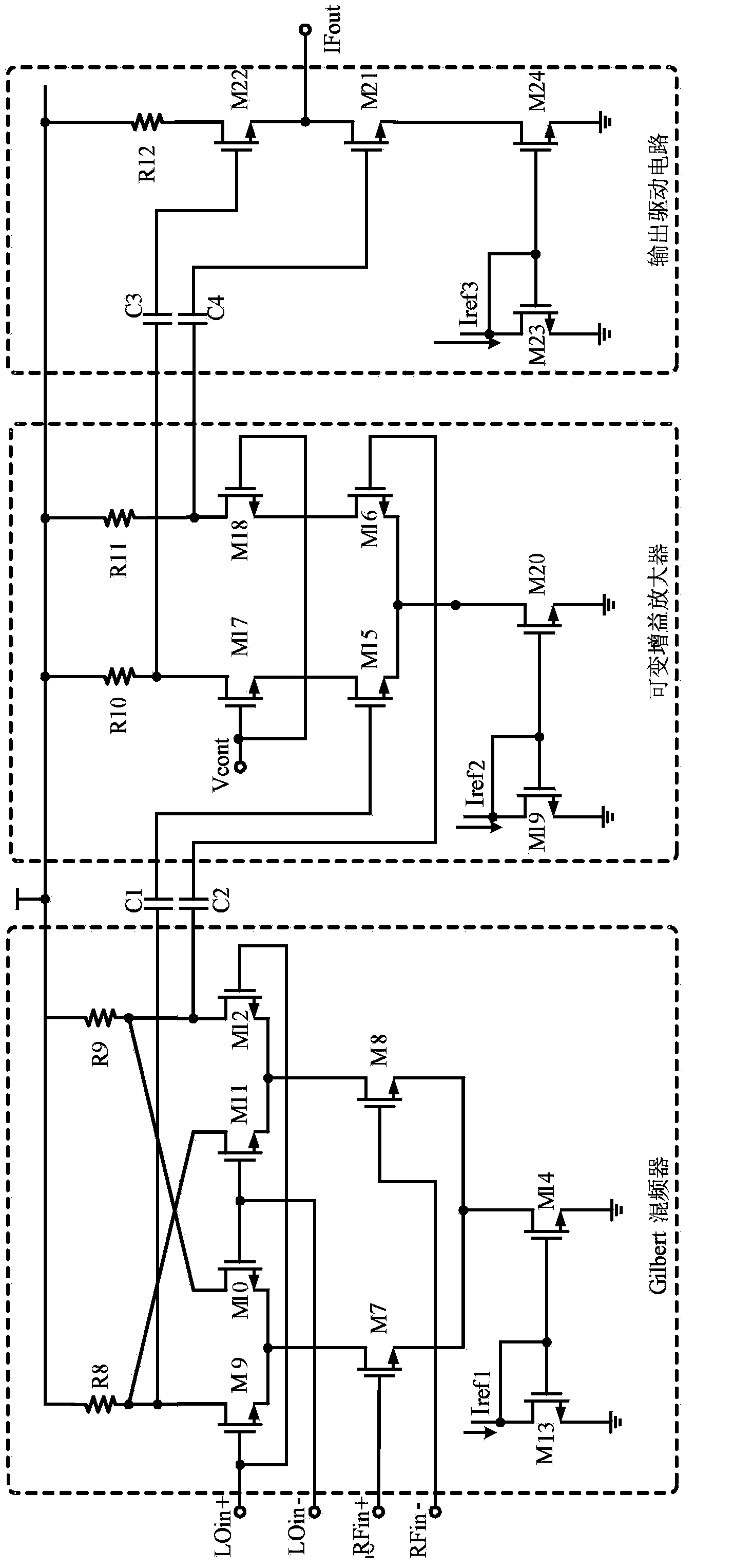
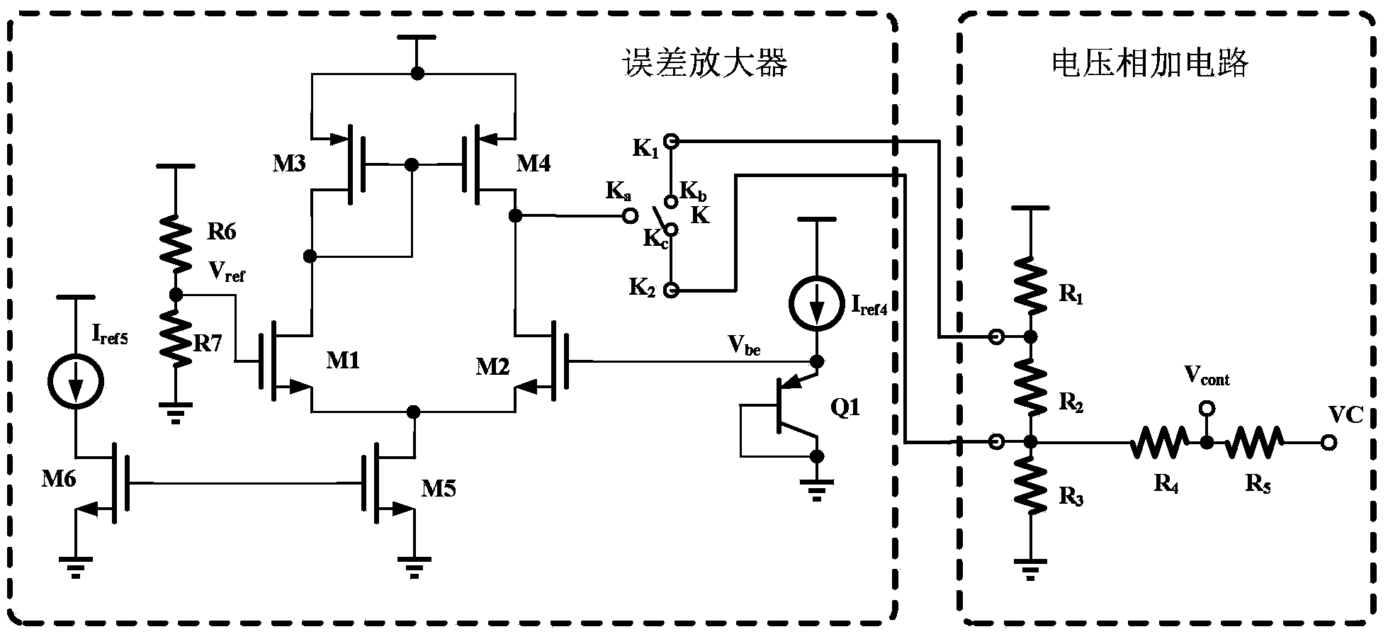
[0030] The CMOS radio frequency receiving front end with wide temperature working gain automatic control function of the present invention is used for the realization of CMOS radio frequency receiving front end chip gain automatic control technology under wide temperature working conditions, see figure 1 The CMOS radio frequency receiving front-end chip includes a radio frequency single-ended-differential conversion circuit 1, a local oscillator single-ended-differential conversion circuit 2, a Gilbert mixer circuit 3, a variable gain amplifier 4, an output drive circuit 5, and a bandgap reference s...


PUM


Abstract

The invention discloses a CMOS radio frequency receiving front end with a wide temperature work gain automatic control function. The front end comprises a radio frequency single end-difference converting circuit, a local oscillator single end-difference converting circuit, a Gilbert frequency mixing circuit, a variable gain amplifier, an output driving circuit, a band gap reference based current bias circuit and a gain automatic control circuit. The radio frequency single end-difference converting circuit and the local oscillator single end-difference converting circuit respectively convert input single-end receiving signals and local oscillator signals into difference signals, the difference output driving the Gilbert frequency mixing circuit is connected with the variable gain amplifier, then difference-single end conversion is carried out through the output driving circuit, and finally intermediate frequency output is performed. The current bias circuit outputs five paths of reference currents from Iref1 to Iref5 respectively to the tail current tube circuits of the Gilbert frequency mixing circuit, the variable gain amplifier, the output driving circuit and the gain automatic control circuit for current biasing.

Description

technical field [0001] The invention relates to a CMOS radio frequency receiving front-end with the function of automatic control of wide temperature working gain. In the radio frequency receiving front-end chip realized based on CMOS technology, the current bias technology based on the bandgap reference source and the temperature self-adaptive gain adjustment method are used to realize the realization The gain automatic control of the whole chip in a wide temperature range is suitable for various radio receiver RF front-end circuits. Background technique [0002] The RF front-end of a radio receiver generally includes basic circuits such as low-noise amplifiers, mixers, variable gain amplifiers, and intermediate frequency amplifiers. When designing these basic circuit units using CMOS technology, the equivalent gain can be expressed as: [0003] G=A·g m_eff · R L [0004] Among them, A is a coefficient related to the circuit type. For example, A is generally 1 in an ampl...

Claims


Application Information

Patent Timeline
IPC IPC(8): H04B1/16H04W52/52H03G3/30
Inventor 段宗明李智群王曾祺王晓东马强
Owner CHINA ELECTRONIC TECH GRP CORP NO 38 RES INST
Learn More