Power converting device

A power conversion device and asymmetric technology, applied in the direction of output power conversion device, AC power input conversion to DC power output, circuit device, etc., can solve the problems of high cost and complex structure, and achieve low cost and compact hardware structure , Realize the effect of time-sharing multiplexing

Active Publication Date: 2014-03-19
SHANDONG INST OF ADVANCED TECH CHINESE ACAD OF SCI CO LTD
View PDF7 Cites 15 Cited by
  • Summary
  • Abstract
  • Description
  • Claims
  • Application Information

AI Technical Summary

Problems solved by technology

[0005] For this reason, the technical problem to be solved by the present invention lies in the driving and charging conversion device of the switched reluctance motor in the prior art. When charging, other devices need to be added, the structure is complicated, and the cost is high. Power conversion device for integrated switched reluctance motor drive and battery charging realized by multiplexing switching devices

Method used


Image

  • Power converting device
  • Power converting device
  • Power converting device

Examples


Embodiment 1

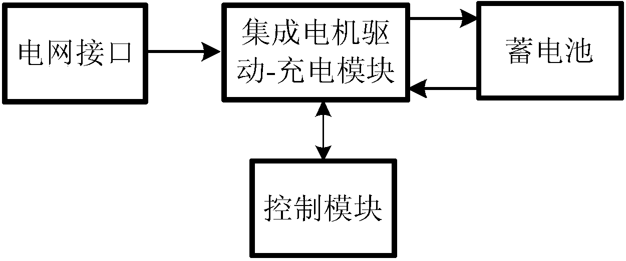
[0032] This embodiment provides a power conversion device, its structural block diagram is as follows figure 1 As shown, the grid interface module and the integrated motor drive-charging module connected to the grid interface module, the battery module connected to the integrated motor drive-charging module, and the control unit connected to the integrated motor drive-charging module module. The grid interface module is responsible for connecting with the peripheral grid and providing power to the charging mode of the integrated motor drive-charging module; the control module controls the work of the integrated motor-charging module according to a preset program to complete the motor drive mode and charging mode. The control of the battery charging mode; the battery provides energy for the motor drive mode, and stores the energy charged by the grid in the charging mode; the integrated motor drive-charging module provides the motor drive mode and the battery charging mode accor...

Embodiment 2

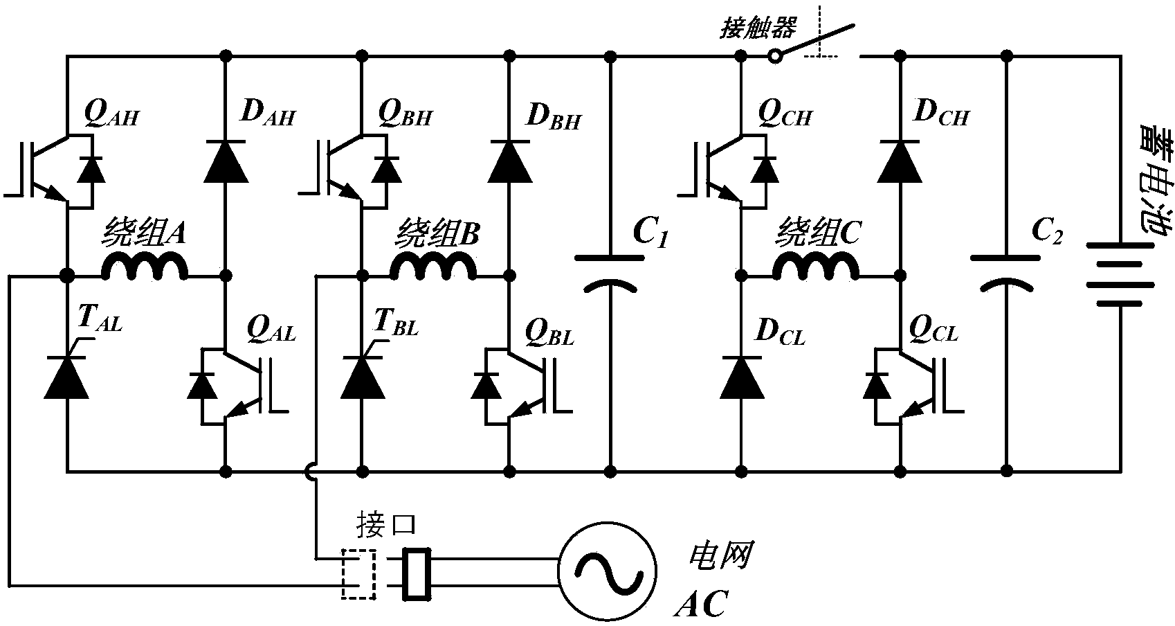
[0051] In this embodiment, a power conversion device is provided, which includes four-phase motor windings. For the specific structure, see Image 6 , including four asymmetrical half-bridge circuits, the asymmetrical half-bridge circuit formed at the A-phase winding and the B-phase winding is a step-up rectifier circuit, and the asymmetrical half-bridge circuit formed at the C-phase and D-phase winding is a lift voltage charging circuit.

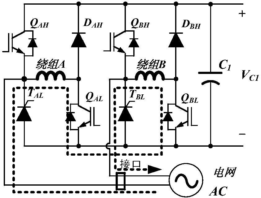
[0052] In the step-up rectification circuit, the asymmetrical half-bridge circuit at winding A at winding B includes: motor winding A, one end of the motor winding A is connected to the power electronic switching device Q AH emitter and thyristor T AL The cathode is connected, and the other end is connected to the power electronic switching device Q AL collector and diode D AH The anode connection of the power electronic switching device Q AH collector of the diode D AH The cathode connection of the power electronic switching device Q ...


PUM


Abstract

The invention provides a power converting device. The power converting device comprises asymmetric half-bridges arranged at each motor winding, wherein two of the asymmetric half-bridges are taken as boost rectifying circuits, diodes at lower portions of the two asymmetric half-bridge circuits are replaced by thyristors, so each of the two asymmetric half-bridge circuits comprises two electric power electronic switch devices (IGBT or MOSFET), one diode, one controllable thyristor and one phase of the motor winding, the other asymmetric half-bridge circuit which is taken as a buck-boost charging circuit comprises two electric power electronic switch devices, two diode, one phase of motor winding and a contactor, and the contactor is arranged between a collector electrode of the upper electric power electronic switch device and a cathode electrode of the upper diode. The power converting device provides a compensation method for static charging of a rotor through hardware topology and software algorithm, so static charging of the charging mode rotor is realized, time division multiplexing of the device is further realized, cost of a component and wiring complexity of a circuit board are greatly reduced, and a hardware structure is made to be more compact.

Description

technical field [0001] The invention relates to a power conversion device for power supply and charging, in particular to a power conversion device integrating switching reluctance motor driving and battery charging. Background technique [0002] Switched reluctance motor is a new type of speed regulation motor. The speed regulation system has the advantages of both DC and AC speed regulation systems. It is the latest generation of stepless speed regulation system following the frequency conversion speed regulation system and brushless DC motor speed regulation system. The driving circuit of the switched reluctance motor in the prior art mainly includes a DC power supply, a DC capacitor, an N-phase motor winding, an upper switching device, a lower switching device, an upper freewheeling diode and a lower freewheeling diode. The main function of the above-mentioned DC capacitor is to provide a buffer for the rectification circuit or the battery, and stabilize the DC bus volta...

Claims


Application Information

Patent Timeline
IPC IPC(8): H02M7/219H02J7/10
Inventor 梁嘉宁徐国卿蹇林旎李卫民常明
Owner SHANDONG INST OF ADVANCED TECH CHINESE ACAD OF SCI CO LTD
Why Eureka
Try Eureka