
A drill rod storage mechanism

A technology of drill pipe storage and drill pipe, which is applied in the direction of drill pipe, drill pipe, drilling equipment, etc., which can solve the problems of difficult installation and installation of drill pipe, high labor intensity of workers, and danger-prone, etc. The operation is difficult and labor-intensive, and the effect of reducing labor intensity

Inactive Publication Date: 2015-08-19
CHINA UNIV OF GEOSCIENCES (WUHAN)
View PDF8 Cites 0 Cited by
  • Summary
  • Abstract
  • Description
  • Claims
  • Application Information

AI Technical Summary

Problems solved by technology

However, the installation operation of installing drill pipes is difficult, inefficient, labor-intensive, and prone to danger. Therefore, it is very important to design an automatic mechanism for changing drill pipes.

Method used


Image

  • A drill rod storage mechanism
  • A drill rod storage mechanism
  • A drill rod storage mechanism

Examples


Embodiment 1

[0034] Embodiment 1: A drill rod magazine mechanism provided by the present invention includes a mechanical part and a hydraulic control part;

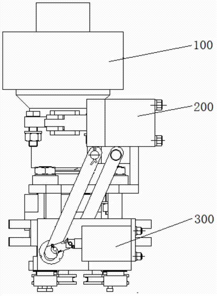
[0035] The mechanical part is composed of a rotating disk mechanism 100, a drill pipe clamping mechanism 200, and a drill pipe conveying mechanism 300; figure 1 shown.

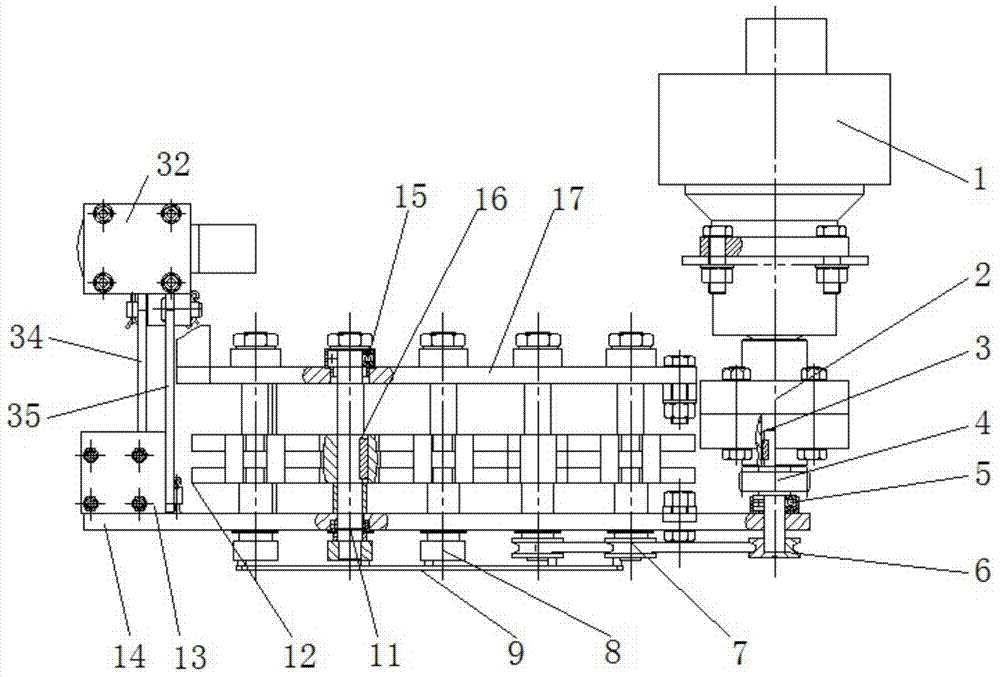
[0036] The rotary disk mechanism 100 is the core part of the design of the whole drill rod magazine. see figure 2, the rotary disc mechanism 100 is provided with a hydraulic motor 1, a shaft coupling 2, a driving gear 3, a driven gear 4, a driven shaft pulley 6, a driven pulley belt 7, a runner 8 and a runner connecting rod A9, a runner connecting rod B10, rotating shaft 11, rotating disk 12, upper support plate 17, lower support plate 14, shaft coupling 2 is installed on the main shaft of described hydraulic motor 1, coupling 2 is connected with driving gear 3, and driving gear 3 is connected with slave The driving gear 4 is meshed, and the driving gear bearing a...


PUM


Abstract

The invention relates to a drill pipe warehouse mechanism. The mechanism comprises a mechanical part, a hydraulic part and a control part, wherein the mechanical part comprises a rotating disk mechanism, a drill pipe conveying mechanism and a drill pipe clamping mechanism; a hydraulic control part comprises a rotating disk mechanism control circuit, a drill pipe conveying mechanism control circuit and a drill pipe clamping mechanism control circuit, the rotating disk mechanism control circuit consists of a solenoid valve A and a hydraulic motor, the drill pipe conveying mechanism control circuit consists of a conveying hydraulic cylinder, a solenoid valve B, a pressure gauge B and a hydraulically-controlled check valve B, the drill pipe clamping mechanism control circuit consists of a clamping hydraulic cylinder, a pressure gauge C, a hydraulically-controlled check valve C, a hydraulically-controlled check valve D and a solenoid valve C, and the hydraulically-controlled check valve C and the hydraulically-controlled check valve D constitute a bi-directional hydraulic lock for clamping a drill pipe. A drill pipe warehouse of the drill pipe warehouse mechanism is closely attached to a drilling frame of a drilling rig, five drill pipes can be carried once by the drill pipe warehouse, and the drill pipes are erected in the drill pipe warehouse mechanism in a linearly-arranged manner. The drill pipe warehouse mechanism is simple in usage method, the drill pipes are taken out of the drill pipe warehouse sequentially through the rotating disk mechanism, and after the drill pipes are clamped by the drill pipe clamping mechanism, the drill pipes are conveyed to a power head part by the drill pipe conveying mechanism.

Description

technical field [0001] The invention relates to a drill rod storage mechanism. Background technique [0002] From the end of the 20th century to the present is a period of rapid development of drilling technology. The development and application of drilling technology has generally been valued by countries all over the world. It is hoped that the development of drilling and excavation industry will drive the development of other related industries. With the rapid development of the world's industry and economy, ensuring safe production, improving work efficiency and reducing labor intensity have become the primary issues, and the highly automated design of drilling rigs has attracted more and more attention. At present, the automatic operation function has been applied in horizontal directional drilling rigs, realizing the automatic extraction, transportation and recovery of drill pipes, drill pipe connection, automatic lubrication, self-contained anchoring system, electric ...

Claims


Application Information

Patent Timeline
Patent Type & Authority Patents(China)
IPC IPC(8): E21B19/14
Inventor 孟瑞冯希江进国
Owner CHINA UNIV OF GEOSCIENCES (WUHAN)
Learn More