Single-switching-tube converter Boost-Buck-Boost converter

A converter and single-tube technology, applied in the field of cascaded DC-DC converters, can solve the problems of complex circuit structure, difficulty in controlling the leakage inductance of transformers and coupled inductors, increase device stress and energy loss, etc., and achieve a simplified circuit structure. Effect

Active Publication Date: 2014-03-12
SOUTH CHINA UNIV OF TECH
View PDF6 Cites 2 Cited by
  • Summary
  • Abstract
  • Description
  • Claims
  • Application Information

AI Technical Summary

Problems solved by technology

At present, high-gain step-up DC-DC converters have switched capacitor type and switched inductor type. The voltage increase is realized by adding switched capacitors or inductors, which also makes the circuit structure very complicated.
In addition, high gain is achieved through isolation transformers or coupled inductors. However, the leakage inductance of transformers and coupled inductors is difficult to control, which will greatly increase the stress and energy loss of the device.
In addition, the cascaded DC-DC converter can achieve high gain and is also very popular. If the basic Boost converter and Buck-Boost converter are cascaded, a high-gain cascaded converter with a simple structure can be obtained. But how to use a switching tube to realize a high-gain cascaded converter is still a difficult problem

Method used


Image

  • Single-switching-tube converter Boost-Buck-Boost converter
  • Single-switching-tube converter Boost-Buck-Boost converter
  • Single-switching-tube converter Boost-Buck-Boost converter

Examples


Embodiment Construction

[0015] In order to further illustrate the content and features of the present invention, the specific embodiments of the present invention will be described in detail below in conjunction with the accompanying drawings. But the implementation of the present invention is not limited thereto.

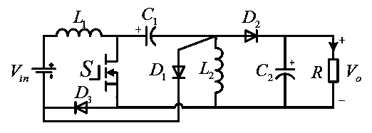
[0016] refer to figure 1 , a single-tube Boost-Buck-Boost converter of the present invention, DC power supply V in , switch tube S, first inductor L 1 , the first diode D 1 , the third diode D 3 and the first capacitor C 1 The Boost converter constituted; with the first capacitor C 1 , switch tube S, second inductance L 2 , the second diode D 2 , the second capacitance C 2 A Buck-Boost converter composed of load R. where the first inductance L 1 One end of the DC voltage V in The positive terminal is connected, the first inductor L 1 The other end is simultaneously connected with the drain of the switch tube S and the first capacitor C 1 The anode is connected; the second ind...


PUM


Abstract

The invention provides a single-switching-tube converter Boost-Buck-Boost converter. According to the invention, an input Boost converter is formed by a DC (Direct Current) power supply (Vin), a switching tube (S), a first diode (D1), a third diode (D3) and a first capacitor (C1); and an output Buck-Boost converter is formed by the first capacitor (C1), the switching tube (S), a second diode (D2), a second capacitor (C2) and a load (R). Cascading of the Boost converter and the Buck-Boost converter is implemented only by using one switching tube (S) and a gain can reach D/(1-D)2. Moreover, an input current of the cascaded converter is continuous, which is very beneficial for filtering the input current.

Description

technical field [0001] The invention relates to the field of cascaded DC-DC converters, in particular to a single-tube Boost-Buck-Boost converter. Background technique [0002] In recent years, high-gain step-up DC-DC converters are widely used in UPS, distributed photovoltaic power generation and battery energy storage systems. At present, high-gain step-up DC-DC converters have switched capacitor type and switched inductor type. The voltage increase is realized by adding switched capacitors or inductors, and the circuit structure is also complicated. In addition, high gain can be achieved through isolation transformers or coupled inductors. However, the leakage inductance of transformers and coupled inductors is difficult to control, which will greatly increase the stress and energy loss of devices. In addition, the cascaded DC-DC converter can achieve high gain and is also very popular. If the basic Boost converter and Buck-Boost converter are cascaded, a high-gain casca...

Claims


Application Information

Patent Timeline
Patent Type & Authority Applications(China)
IPC IPC(8): H02M3/07
Inventor 张波付坚丘东元肖文勋黄子田
Owner SOUTH CHINA UNIV OF TECH
Why Eureka
Try Eureka