
A large-capacity well-type solar heat collection-heat storage device

A technology of solar heat collection and heat storage device, applied in the field of solar heat collection and heat storage, can solve the problems of increasing equipment investment cost, increasing operation and maintenance cost, heat transfer system consumption, etc., so as to reduce investment cost and equipment operation and maintenance cost. , the effect of small footprint and large heat storage capacity

Inactive Publication Date: 2017-01-18
QINGHAI UNIVERSITY
View PDF10 Cites 0 Cited by
  • Summary
  • Abstract
  • Description
  • Claims
  • Application Information

AI Technical Summary

Problems solved by technology

This heat transfer and heat storage mode has the following problems: (1) pumps, related pipelines, heat transfer oil or molten salt are required to transport heat transfer medium, which increases the initial investment cost of equipment; (2) the operation of heat transfer system requires Consuming extra energy, the solar energy focus point of the tower structure is located in the mid-air near up to 100m, and the equipment and heat transfer medium need to be regularly maintained or replaced, which undoubtedly increases the operation and maintenance cost; (3) For high-temperature heat collection and storage systems At present, molten salt is mainly used as the heat transfer medium. The most serious problem is that when the temperature is low at night, the molten salt solidifies and freezes in the heat transfer pipe.
But it cannot fundamentally solve the problem; at the same time, it will undoubtedly increase the operating cost

Method used


Image

  • A large-capacity well-type solar heat collection-heat storage device
  • A large-capacity well-type solar heat collection-heat storage device
  • A large-capacity well-type solar heat collection-heat storage device

Examples


Embodiment 1

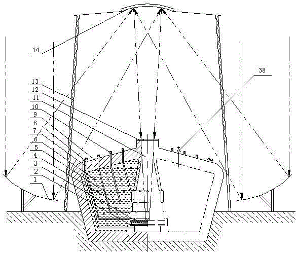
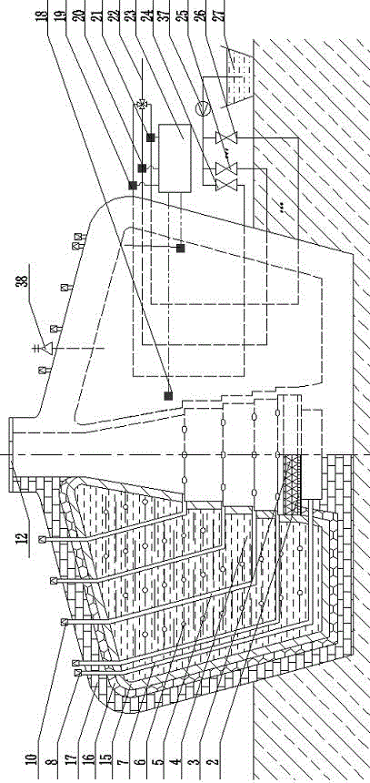
[0029] Such as figure 1 As shown, the primary reflector 1 is a concave reflector with a large radius of curvature, which is fixed on the ground and equipped with a sun tracker, and multiple primary reflectors form a reflector array. The direct solar radiation is projected onto the secondary reflector 14 after being focused by the primary reflector 1 , and the secondary reflector 14 is also a concave reflector, which is fixed high in the sky by a rigid bracket 13 . After the radiation is reflected and focused twice by the secondary reflector 14, it is projected into the sun well 11 through the sun well cover 12, and the focus falls on the heat absorber 3 at the bottom of the well. The sun well cover 12 is a disc-shaped thin plate with a hole in the middle, which can be made of high temperature resistant glass with good light transmission; the sun well 11 is conical, so that the high-density sun entering the well will corrode to produce a blackbody effect and improve heat absorp...


PUM


Abstract

The invention relates to the field of solar heat collection and storage technologies and discloses a high-temperature large-capacity well type solar heat collection-storage device. A primary reflector of the large-capacity well type solar heat collection-storage device is a concave mirror reflector, and a plurality of the primary reflectors are fixed on the ground to form a reflector array; a secondary reflector is mounted in the air and is a convex mirror reflector which is opposite to the primary reflectors, a conical solar well is arranged below the secondary reflector, and a heat absorbing body is arranged at the bottom of the solar well; a heat storage tank body is a hollow tank body, the middle of the heat storage tank body is the solar well, a part of the heat storage tank body is buried underground and is filled with a heat storage medium; a hot air pipe and a cold air pipe penetrate through the heat storage tank body, are immersed into the heat storage medium and are communicated with the air above the solar well and the heat storage tank body; pipe mouths, which are located on the sidewall of the solar well, of the hot air pipe and the cold air pipe are respectively located above and below the heat absorbing body. The large-capacity well type solar heat collection-storage device integrates advantages of point focus heat collection and fuse salt heat storage, does not need a specific heat transfer system, and has the advantages of simple structure, low maintenance cost, large heat storage capacity, small floor space and more artistic form.

Description

technical field [0001] The invention relates to the technical field of solar heat collection and heat storage, in particular to a high-temperature and large-capacity well-type solar heat collection-heat storage device. Background technique [0002] As a renewable energy with large reserves, clean and pollution-free, solar energy has a broad space for development. Photothermal utilization technology is one of the forms of solar energy utilization, such as solar water heating system, solar heating system, solar steam generator, solar thermal power generation and other technologies. However, solar energy has the characteristics of dispersion and intermittency: the direct radiation energy flux density projected on the unit ground area is low; moreover, the direct radiation is interrupted during the cloud cover period and after sunset, which limits the popularization and application of related technologies. [0003] At present, many researchers have provided a variety of heat co...

Claims


Application Information

Patent Timeline
Patent Type & Authority Patents(China)
IPC IPC(8): F24J2/10F24J2/26F24J2/34F24J2/46F24S10/75F24S23/70
CPCF24S20/20F24S23/79F24S60/00Y02E10/40
Inventor 王军伟金培鹏雷富军郭彦宏李戬王金辉曹海莲高莉郭强马秀玲
Owner QINGHAI UNIVERSITY
Learn More