Carbon crystal electric warming mat

A carbon crystal and electric heating technology, which is applied in the direction of electrical components, electric heating systems, electric heating devices, etc., can solve the problems of low energy consumption, inability to use safe voltage, and inability to achieve high and low temperature gear control, etc., to achieve low energy consumption Effect

Inactive Publication Date: 2014-03-12
SUZHOU JUNYA ELECTRONICS
View PDF6 Cites 2 Cited by
  • Summary
  • Abstract
  • Description
  • Claims
  • Application Information

AI Technical Summary

Problems solved by technology

[0003] Aiming at the deficiencies in the above-mentioned prior art, the main purpose of the present invention is to provide a carbon crystal electric heating pad, which solves the problem that ordinary electric heating pads cannot use a safe voltage below 36V and that when using a safe voltage of 36V, It can't reach the high and low temperature gear control and other deficiencies, and the energy consumption is low; it also overcomes the dangers of heat accumulation, fire, radiation, etc. after long-term use of ordinary electric heating pads; people will not feel discomfort such as dry mouth and tongue after long-term use symptom

Method used


Image

  • Carbon crystal electric warming mat
  • Carbon crystal electric warming mat
  • Carbon crystal electric warming mat

Examples


Embodiment 1

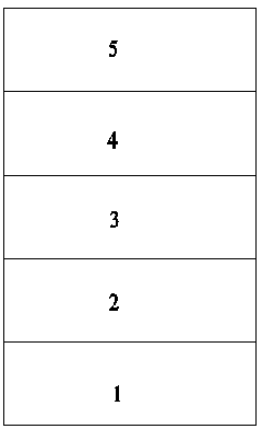
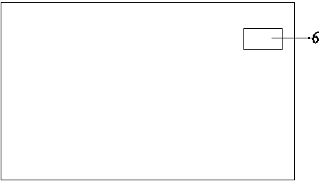
[0030] Embodiment 1: A carbon crystal electric heating pad, the carbon crystal electric heating pad includes a five-layer structure, and the five-layer structure is an anti-slip layer 1, a first adhesive layer 2, and a PTC constant temperature double-sided structure from bottom to top. Heating layer 3, second adhesive layer 4, and decorative layer 5; the first adhesive layer 2 bonds the non-slip layer 1 to one side of the PTC constant temperature double-sided heating layer 3; the second adhesive layer 4 bonds the PTC constant temperature double-sided heating The other side of the layer 3 is bonded to the decorative layer 5; the PTC constant temperature double-sided heating layer 3 is provided with electrodes, and the carbon crystal electric heating pad is provided with a control switch 6, and the control switch 6 is connected to the electrodes of the PTC constant temperature double-sided layer 3.

[0031] In this embodiment, the PTC constant temperature double-sided heating lay...

Embodiment 2

[0041] Embodiment 2: The difference between this embodiment and Embodiment 1 is that in this embodiment, the side of the first PTC heating sheet printed with the first PTC heating carbon paste is covered with a protective film. The film is combined with the first layer of PTC heating sheet; the side of the second layer of PTC heating sheet printed with the second PTC heating carbon paste is covered with a protective film, and the protective film and the second layer of PTC The heating sheet is combined into one body. The protective film is made of polyester material.

Embodiment 3

[0042] Embodiment 3: The difference between this embodiment and Embodiment 1 is: in this embodiment, the spacing between the plurality of electrode lines on the first layer of PTC heating sheet is 100mm; the plurality of electrode lines on the second layer of PTC heating sheet The spacing between the root electrode wires is 100mm.


PUM

PropertyMeasurementUnit
electrical resistanceaaaaaaaaaa

Abstract

The invention discloses a carbon crystal electric warming mat which comprises a five-layer structure. An anti-sliding layer and one face of a PTC constant temperature two-sided heating layer are glued through a first gluing layer, the other face of the PTC constant temperature two-sided heating layer and a decoration layer are glued through a second gluing layer, an electrode is arranged in the PTC constant temperature two-sided heating layer, a control switch is arranged on the carbon crystal electric warming mat, and the control switch is connected with the electrode of the PTC constant temperature two-sided heating layer. By means of the mode, the shortcomings that a safe voltage lower than 36V cannot be used in a common carbon crystal electric warming mat, and gear control at the high temperature and the low temperature cannot be achieved under the condition that a 36V safe voltage is used are overcome, and the energy consumption is low; risks, such as temperature gathering, fire catching and radiation, of the common carbon crystal electric warming mat after long-time use are overcome, and the mouth parched and tongue scorched discomfort symptoms and the like of people after long-time use are avoided.

Description

technical field [0001] The invention relates to an electric heating device, in particular to a carbon crystal electric heating pad which is used for laying the ground of homes and workplaces and has a heating function. Background technique [0002] With the development of society, people's living standards have been greatly improved. In the cold winter, many families are no longer satisfied with the heating mode of the air conditioner, but are pursuing a healthier and more convenient heating method. The electric heating pad is favored by users because of its flexible and convenient use, safe and reliable laying. However, the electric heating pads in the prior art generally use ordinary metal resistance wires or carbon fibers as heating elements to make electric heating pads, and there are also two parallel electrodes made on polyester films, and parallel, regular ordinary carbon electrodes are printed. The slurry wire connects two electrodes as a heating element, and final...

Claims


Application Information

Patent Timeline
Patent Type & Authority Applications(China)
IPC IPC(8): F24D13/02F24D19/10H05B3/36B32B33/00
Inventor 姚鉴恒
Owner SUZHOU JUNYA ELECTRONICS
Why Eureka
Try Eureka