
MOCVD apparatus and MOCVD heating method

A technology of equipment and trays, applied in chemical instruments and methods, gaseous chemical plating, crystal growth, etc., can solve the problems of film growth speed difference, uneven temperature, inconsistent deposited film, etc., and realize the processing of large-size substrates , Improve temperature uniformity, improve the effect of growth quality

Active Publication Date: 2014-03-12
BEIJING NAURA MICROELECTRONICS EQUIP CO LTD
View PDF3 Cites 10 Cited by
  • Summary
  • Abstract
  • Description
  • Claims
  • Application Information

AI Technical Summary

Problems solved by technology

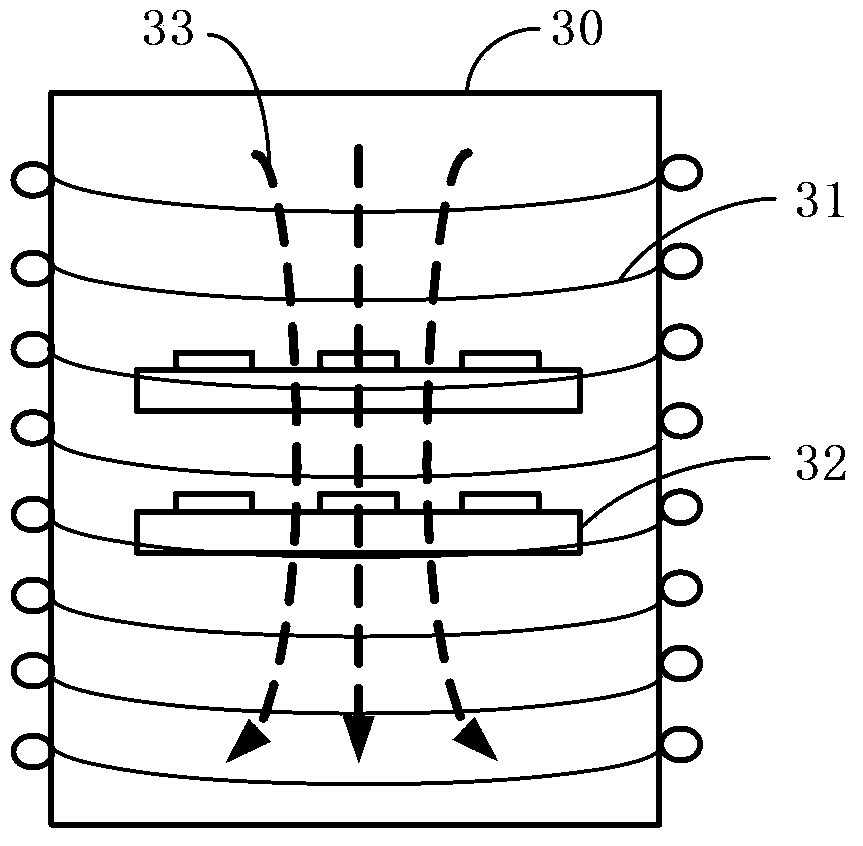
It can be seen from the figure that the distribution of the lines of magnetic force 41 in the magnetic field is not uniform. Specifically, the distribution of the lines of magnetic force 41 changes from sparse to dense from the center position inside the reaction chamber to the edge position, while the uneven distribution of the lines of magnetic force 41 It will cause uneven temperature on the surface of the tray. For the tray concentrically arranged with the induction coil 40, the peripheral temperature of the tray surface will be higher, and the middle temperature will be lower. The above phenomenon will cause the following problems in the induction heating method: the tray surface The temperature change will cause the growth temperature of the substrate placed in different positions on the tray to be different, and the different growth temperature of the substrate will cause the difference in the film growth rate and the inconsistency of the deposited film.
Furthermore, when growing a multi-layer heterostructure, the gas inlet device in the reaction chamber will uniformly change the composition to grow the multi-layer heterostructure, but the growth speed of each substrate is inconsistent. With the uniform composition transformation, it will lead to Its multilayer heterogeneous structure is different, so the consistency of the thin film generated on the substrate cannot be guaranteed
[0007] To sum up, the uneven distribution of magnetic force lines causes uneven surface temperature of the tray, which cannot guarantee the quality of film growth on the substrate.

Method used


Image

  • MOCVD apparatus and MOCVD heating method
  • MOCVD apparatus and MOCVD heating method
  • MOCVD apparatus and MOCVD heating method

Examples


Embodiment Construction

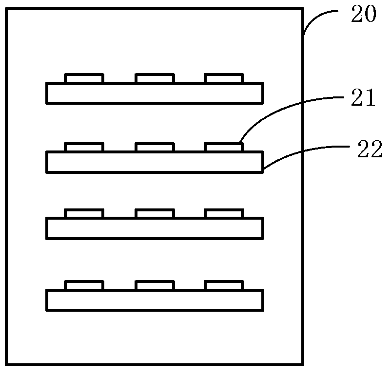
[0037] In order to enable those skilled in the art to better understand the technical solution of the present invention, the MOCVD equipment and the heating method of the MOCVD equipment provided by the embodiments of the present invention will be described in detail below with reference to the accompanying drawings.

[0038] The invention provides an MOCVD device, which includes a reaction chamber, an induction coil and a tray. In addition to the above structure, MOCVD equipment also includes gas delivery system, tail gas treatment system and other devices.

[0039]Among them, the MOCVD equipment is a kind of induction heating MOCVD equipment, the induction coil is located outside the reaction chamber, and the induction coil is connected with the RF power supply of medium and high frequency, which is used to generate a magnetic field during the process and pass the magnetic field to the reaction chamber. The tray is heated. The present invention utilizes the distribution law...


PUM


Abstract

The present invention discloses a MOCVD apparatus and a MOCVD heating method. The MOCVD apparatus comprises a reaction chamber, an induction coil and a tray, wherein the induction coil is positioned outside the reaction chamber, the tray is positioned inside the reaction chamber, the induction coil is provided for generating a magnetic field and heating the tray through the magnetic field, and the tray is provided for placing a substrate and generating a relative movement between the tray and the magnetic field so as to make the substrate alternately pass through the magnetic force line sparse area and the magnetic force line dense area in the magnetic field. According to the embodiment of the present invention, the substrate on the tray alternately passes through the magnetic force line sparse area and the magnetic force line dense area in the magnetic field, such that heating temperatures of different areas on the tray are uniform, and temperature uniformity on the substrate is increased so as to improve epitaxial wafer quality and achieve large epitaxial wafer processing.

Description

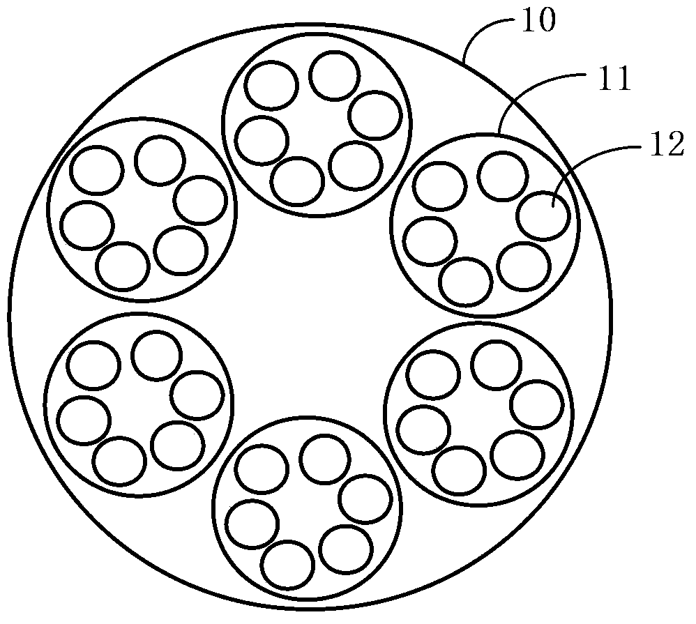
technical field [0001] The invention relates to semiconductor technology, in particular to an MOCVD device and a MOCVD heating method. Background technique [0002] MOCVD (Metal-organic Chemical Vapor Deposition, metal-organic compound chemical vapor deposition) is a growth technology for vapor phase epitaxy on a substrate by thermal decomposition reaction through crystal growth source materials. MOCVD equipment is a device that deposits thin films on the surface of a substrate using MOCVD technology. When using MOCVD equipment for thin film deposition, the process time is relatively long, typically, 5-6 hours to complete a complete process. [0003] In order to improve the production efficiency of MOCVD equipment, a placement method that can place multiple substrates at the same time is adopted. At present, one of the main methods used is the large tray method. Please refer to figure 1 , wherein, a plurality of small trays 11 are placed on the large tray 10, and a plurali...

Claims


Application Information

Patent Timeline
IPC IPC(8): C23C16/44C23C16/46C30B25/10C30B25/02
Inventor 张慧
Owner BEIJING NAURA MICROELECTRONICS EQUIP CO LTD
Learn More