Diamond arc plate band-sawing machine
A technology of circular arc plate and band saw machine, which is applied in the field of diamond circular arc plate band saw machine, and can solve the problems such as the inability to adjust the displacement of the output shaft of the steering gear of the saw rack, the inability to cut stones and sizing the circular arc plate, and increase the waste of stones, etc.
- Summary
- Abstract
- Description
- Claims
- Application Information
AI Technical Summary
Problems solved by technology
Method used
Image
Examples
Embodiment 1
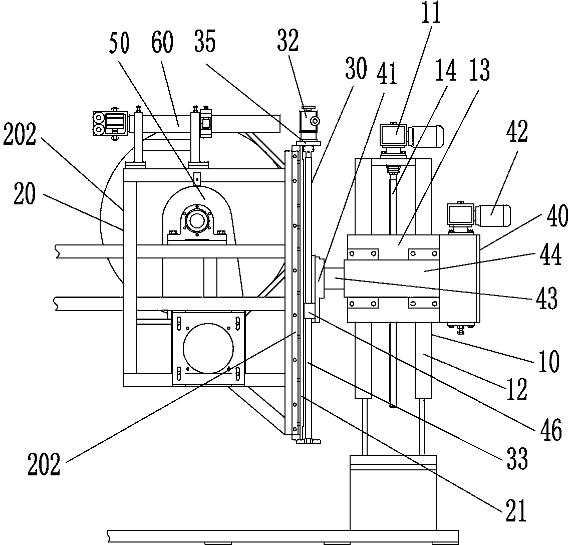
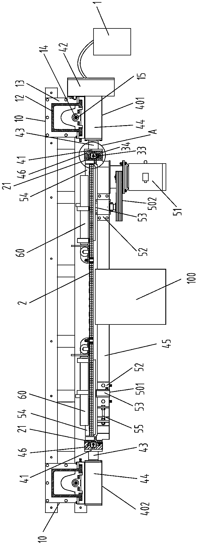
[0025] combine Figure 1~3 , a diamond arc plate band saw machine, comprising an electrical control system 1, a lifting column 10, a saw frame 20 and a sizing adjustment device 30; the side of the lifting column 10 is fixedly provided with a rotating device 40; Lan 41 transmission connection; sizing adjustment device 30 is made up of lifting drive device 32, first screw mandrel 33 and first nut 34; The first nut 34 is sleeved; the first nut 34 is fixedly connected with the rotating flange 41; the first screw rod 32 is rotated outside and the end plate 35 is sleeved, and the saw frame 20 is fixedly connected with the end plate 35; two rotary devices are set up on the saw frame 20 50, the saw band 2 is tensioned between the two rotary devices 50, and both the rotary device 40 and the rotary device 50 are connected to the electric control system 1 circuit.
[0026]Before the cutting work, according to the height of the stone, the rotating device 40, the sizing adjustment device ...
Embodiment 2
[0031] Embodiment 2 is different from Embodiment 1 in that: as Image 6 As shown, two normal guide wheels 71 are rotatably installed on the guide wheel frame 67, and the normal guide wheels 71 are arranged on both sides of the saw band 2 respectively. In this way, the normal guide wheel 71 can limit and guide both sides of the saw band 2 in the arc tangential direction.
[0032] Both Embodiment 1 and Embodiment 2 of the present invention can be improved as follows.
[0033] In the specific implementation process, such as image 3 As shown, the rotating flange 41 is provided with a fixed guide rail 46 along the length direction of the first screw mandrel 33, and the first nut 34 is fixedly connected with the fixed guide rail 46, that is, the first nut 34 is fixedly connected with the rotating flange 41 through the fixed guide rail 46; The bottom of end plate 35 is fixedly provided with a movable guide rail 21, and movable guide rail 21 is fixedly connected with saw frame 20, ...
PUM
 Abstract
Description
Claims
Application Information
 - R&D
- Intellectual Property
- Life Sciences
- Materials
- Tech Scout
- Unparalleled Data Quality
- Higher Quality Content
- 60% Fewer Hallucinations
Browse by: Latest US Patents, China's latest patents, Technical Efficacy Thesaurus, Application Domain, Technology Topic, Popular Technical Reports.
© 2025 PatSnap. All rights reserved.Legal|Privacy policy|Modern Slavery Act Transparency Statement|Sitemap|About US| Contact US: help@patsnap.com


