Planar Horn Antenna with Thin Substrate Phase Corrected Quasi-Yagidine Beam

A horn antenna and phase correction technology, applied in waveguide horns, radiating element structures, circuits, etc., can solve the problems of low gain, radiation directivity and gain reduction, phase asynchrony, etc. The effect of small electrical loss and compact structure

Inactive Publication Date: 2016-03-23
SOUTHEAST UNIV
View PDF6 Cites 0 Cited by
  • Summary
  • Abstract
  • Description
  • Claims
  • Application Information

AI Technical Summary

Problems solved by technology

In addition, the gain of the traditional substrate-integrated waveguide planar horn antenna is relatively low. The reason is that due to the continuous opening of the horn mouth, the phase is out of sync when the electromagnetic wave propagates to the horn aperture surface, and the radiation directivity and gain are reduced. The zero depth of the difference beam antenna is shallow and the slope is low, which affects the direction finding accuracy of the radar
At present, methods such as dielectric loading and dielectric prisms have been used to correct the horn aperture field, but these phase alignment structures increase the overall structural size of the antenna

Method used


Image

  • Planar Horn Antenna with Thin Substrate Phase Corrected Quasi-Yagidine Beam

Examples


Embodiment Construction

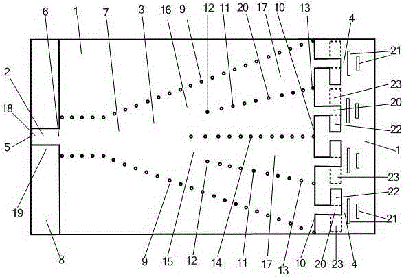
[0023]The embodiment that the present invention adopts is: the thin substrate phase correction quasi-Yagi difference beam planar horn antenna includes the microstrip feeder 2 that is arranged on the dielectric substrate 1, the substrate integrated horn antenna 3 and a plurality of quasi-Yagi antennas 4; The first port 5 of the microstrip feeder 2 is the input and output port of the antenna, and the second port 6 of the microstrip feeder 2 is connected to the substrate integrated horn antenna 3; A metal plane 7, a second metal plane 8 located on the other side of the dielectric substrate 1, and two rows of metallized via hole horn sidewalls 9 passing through the dielectric substrate 1 to connect the first metal plane 7 and the second metal plane 8, the substrate The width between the two rows of metallized via holes on the horn side walls 9 of the integrated horn antenna 3 gradually increases to form a horn-shaped opening, and the end of the opening is the aperture surface 10 of...


PUM


Abstract

The invention relates to a planar horn antenna with a thin substrate phase correction quasi-Yagidifference beam and relates to a horn antenna. The antenna includes a microstrip feeder (2), a horn antenna (3) and a quasi Yagi antenna (4) on a dielectric substrate (1). The horn antenna (3) consists of a first metal plane (7), a second metal plane ( 8) and two rows of metallized via-hole horn sidewalls (9), there are an odd number of metallized via-hole arrays (11) and an even number of dielectric-filled waveguides (17) in the horn antenna (3), and the horn antenna (3) Each dielectric-filled waveguide (17) on the aperture surface (10) is connected with a quasi-Yagi antenna (4) composed of an active oscillator (20) and a passive oscillator (21), the left half antenna (15) and the connected quasi-yagi The Yagi antenna (4) is symmetrical with the right half antenna (16) and the connected quasi Yagi antenna (4). Electromagnetic waves can reach the quasi-Yagi antenna in the same phase and then radiate, and the radiation field polarization is parallel to the substrate. The antenna can use a thin substrate and has high gain, large zero depth, low cost and compact structure.

Description

technical field [0001] The invention relates to a horn antenna, in particular to a planar horn antenna with a thin substrate phase correction quasi-Yagidifference beam. Background technique [0002] Horn antennas are widely used in systems such as satellite communications, ground microwave links, and radio telescopes. However, the huge geometric size of the three-dimensional horn antenna restricts its application and development in planar circuits. In recent years, the proposal and development of substrate-integrated waveguide technology have greatly promoted the development of planar horn antennas. The substrate-integrated waveguide has the advantages of small size, light weight, easy integration and fabrication. The planar substrate-integrated waveguide horn antenna based on the planar substrate-integrated waveguide not only has the characteristics of the horn antenna, but also realizes the miniaturization and light weight of the horn antenna, and is easy to integrate in...

Claims


Application Information

Patent Timeline
Patent Type & Authority Patents(China)
IPC IPC(8): H01Q13/02H01Q1/38
Inventor 殷晓星赵洪新汪源
Owner SOUTHEAST UNIV
Why Eureka
Try Eureka