Al technical title is built by PatSnap Al team. It summarizes the technical point description of the patent document.
A weapon system, electronic ignition technology, applied in the field of weapons, can solve the problems of unpublished technical details, affecting accuracy, melting the barrel, etc., to achieve the effect of improving the resistance to voltage breakdown, being convenient to carry, and increasing combat effectiveness
Inactive Publication Date: 2014-02-26
刘伟
View PDF0 Cites 0 Cited by
Summary
Abstract
Description
Claims
Application Information
AI Technical Summary
This helps you quickly interpret patents by identifying the three key elements:
Problems solved by technology
Method used
Benefits of technology
Problems solved by technology
[0002] Most of the current guns use mechanical ignition, which has a complex structure and is easy to jam, and the accuracy of the barrel is likely to be affected by the heating of the barrel for a long time, and may even melt the barrel; the currently known electronic ignition gun is the "Metal Storm" in Australia. , they did not announce the technical details, the invention looks similar to Metal Storm from the outside, but I don’t know if the inside is the same
Method used
Image
Click on the blue label to locate the original text in one second.
Reading with bidirectional positioning of images and text.
Examples
Embodiment 1
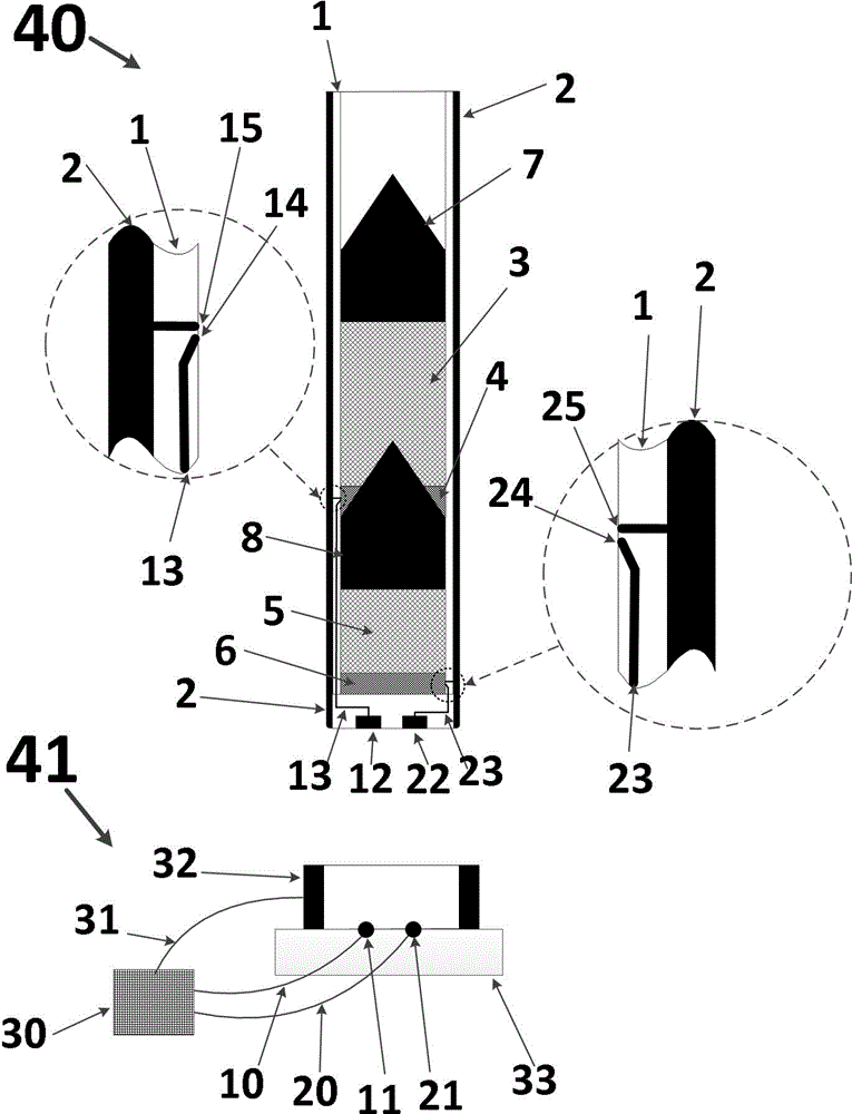
[0022] Such as figure 1 One of the present invention is the basic schematic diagram of the implementation example, which is a replaceable gun with a launch tube 40, two bullets are arranged in each tube, and special ceramics are used as the heat-resistant and wear-resistant insulating inner layer of the launch tube 40- That is, the ceramic inner layer 1 .
[0023] Such as figure 1 As shown, this embodiment is composed of a gun barrel 40 and a base 41, and the gun barrel 40 and the base 41 are detachably connected to facilitate replacement of the gun barrel.
[0024] Such as figure 1 Shown, gun barrel 40 is made of ceramic inner layer 1, metal outer layer 2, gunpowder 3, primer 4, gunpowder 5, primer 6, bullet 7, bullet 8, contact 12, wire 13, wire leakage point 14, metal outer layer Leak point 15, contact 22, wire 23, lead wire leak point 24, metal outer layer leak point 25 constitute.
[0025] Such as figure 1 As shown, the base 41 is composed of a control circuit 30 , a...
Embodiment 2
[0030] On the basis of implementing the principle of example 1, warheads are increased to seven.
[0031]
Embodiment 3
[0033] On the basis of implementing the principle of Example 2, a metal fusion bonding structure is set in the ignition area. When the bullet in this section is fired, the metal melting connects the corresponding wire of the bullet in this section to the outer layer of the metal to form a loop, so that the control circuit can judge the bullet. Whether the launch is successful, prevent the ignition of the rear section after the failure of the front section to cause the launch tube to explode.
[0034]
PUM
Abstract
The invention discloses an electronic ignition weapon system. The electronic ignition weapon system mainly consists of a launching tube and a control circuit; the launching tube is composed of a metal outer layer and a heat-resisting wear-resisting insulation inner layer, and a conducting wire is arranged in the wall of the heat-resisting wear-resisting insulation inner layer; a plurality of bullets are arranged in the launching tube, and gunpowder is filled among the bullets; the metal outer layer is provided with a metal exposure point in a gunpowder area, and the conducting wire is exposed nearby the metal outer layer exposure point to form an ignition area; the control circuit is provided with a function for generating high-voltage power, the ground point of the control circuit is connected to the metal outer layer of the launching tube, and the high-voltage output end of the control circuit is connected to the conducting wire in the wall of the heat-resisting wear-resisting insulation inner layer. The principle of the electronic ignition weapon system is as follows: the gunpowder is ignited through the high-voltage spark, so that the bullets can be launched. The electronic ignition weapon system has beneficial effects that compared with the traditional weapon, the electronic ignition weapon system has the characteristics of stability, reliability and convenience in carrying and is especially suitable for guns and artilleries. If the electronic ignition weapon system is vastly applied in the military of China, the fighting capacity of the military can be enhanced.
Description
technical field [0001] An electronic ignition weapon system is used for war, is an electronically controlled weapon device, and belongs to the field of weapons. Background technique [0002] Most of the current guns use mechanical ignition, which has a complex structure and is easy to jam, and the accuracy of the barrel is likely to be affected by the heating of the barrel for a long time, and may even melt the barrel; the currently known electronic ignition gun is the "Metal Storm" in Australia. , they did not publish the technical details, the invention looks similar to the metal storm from the outside, but it is not known whether the inside is the same. Contents of the invention [0003] The purpose of the present invention is to aim at the deficiencies in the prior art, design a kind of weapon system of electronic ignition, can strengthen the combat effectiveness of our army. [0004] The present invention has the following technical content. [0005] Technical c...
Claims
Application Information
Patent Timeline
Application Date:The date an application was filed.
Publication Date:The date a patent or application was officially published.
First Publication Date:The earliest publication date of a patent with the same application number.
Issue Date:Publication date of the patent grant document.
PCT Entry Date:The Entry date of PCT National Phase.
Estimated Expiry Date:The statutory expiry date of a patent right according to the Patent Law, and it is the longest term of protection that the patent right can achieve without the termination of the patent right due to other reasons(Term extension factor has been taken into account ).
Invalid Date:Actual expiry date is based on effective date or publication date of legal transaction data of invalid patent.