
Vertical mill device for milling ceramic raw materials

A ceramic raw material and grinding technology, applied in grain processing and other directions, can solve the problems affecting the discharge of the hopper and the working efficiency of equipment, insufficient grinding of grinding materials, and disorderly discharge methods, etc., to improve service life and increase grinding. time, the effect of improving the crushing rate

Active Publication Date: 2014-02-26
GUANGDONG BOFFIN MECHANICAL & ELECTRICAL CO LTD
View PDF8 Cites 5 Cited by
  • Summary
  • Abstract
  • Description
  • Claims
  • Application Information

AI Technical Summary

Problems solved by technology

[0002] In the existing vertical mill equipment for ceramic raw materials, the ceramic raw materials are directly dropped to the end surface of the rotating millstone below the hopper through the drop hopper, and the ceramic raw materials near the center of the millstone are difficult to move from the center of the millstone to the center of the millstone due to the small centrifugal force. Grinding area of ​​the grinding disc, resulting in the accumulation of ceramic raw materials in the center of the grinding disc, affecting the discharge of the hopper and the working efficiency of the equipment; and the rollers used in the existing vertical mill, the surface of the roller roller is close to a smooth smooth surface, which is in contact with the grinding disc When the grinding material is used, the grinding material is easy to move on its smooth smooth surface, and when the moisture content of the grinding material is high, the ground material is easily pressed into a cake shape, resulting in insufficient grinding of the grinding material; and the existing The discharge method of the grinding material is only by means of the centrifugal force generated by the rotating grinding disc. This kind of material discharge method is disorderly, which affects the powder discharge rate of the material and reduces the working efficiency of the equipment.

Method used


Image

  • Vertical mill device for milling ceramic raw materials
  • Vertical mill device for milling ceramic raw materials
  • Vertical mill device for milling ceramic raw materials

Examples


Embodiment Construction

[0012] The present invention will be further described below in conjunction with specific embodiment:

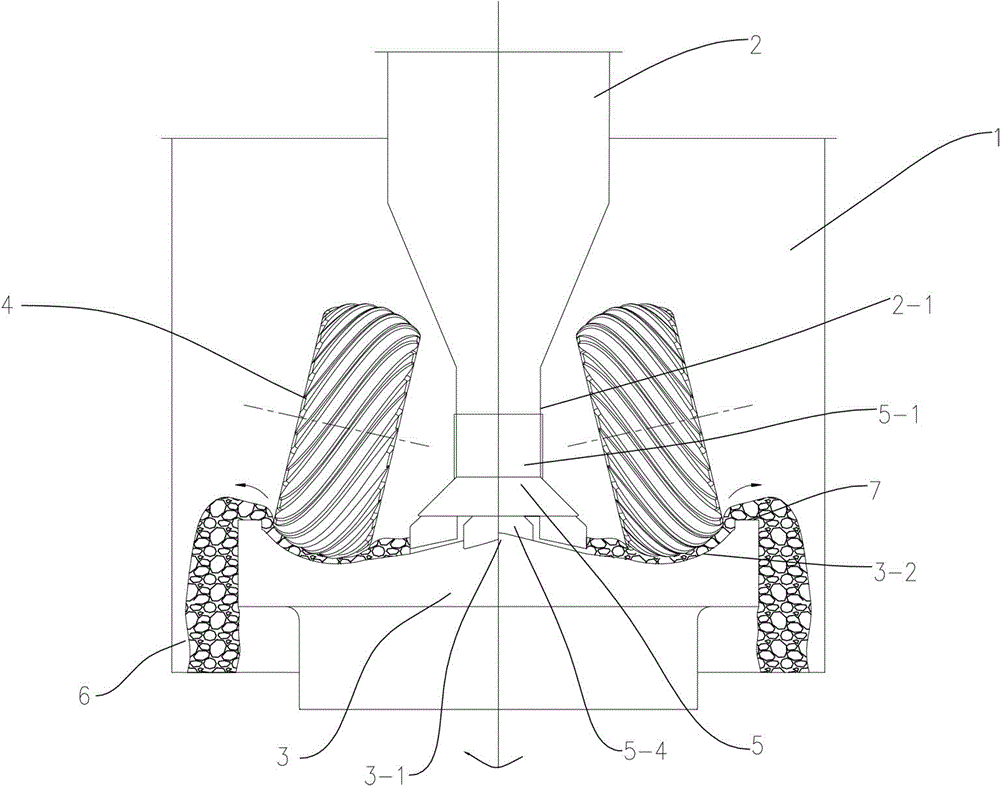
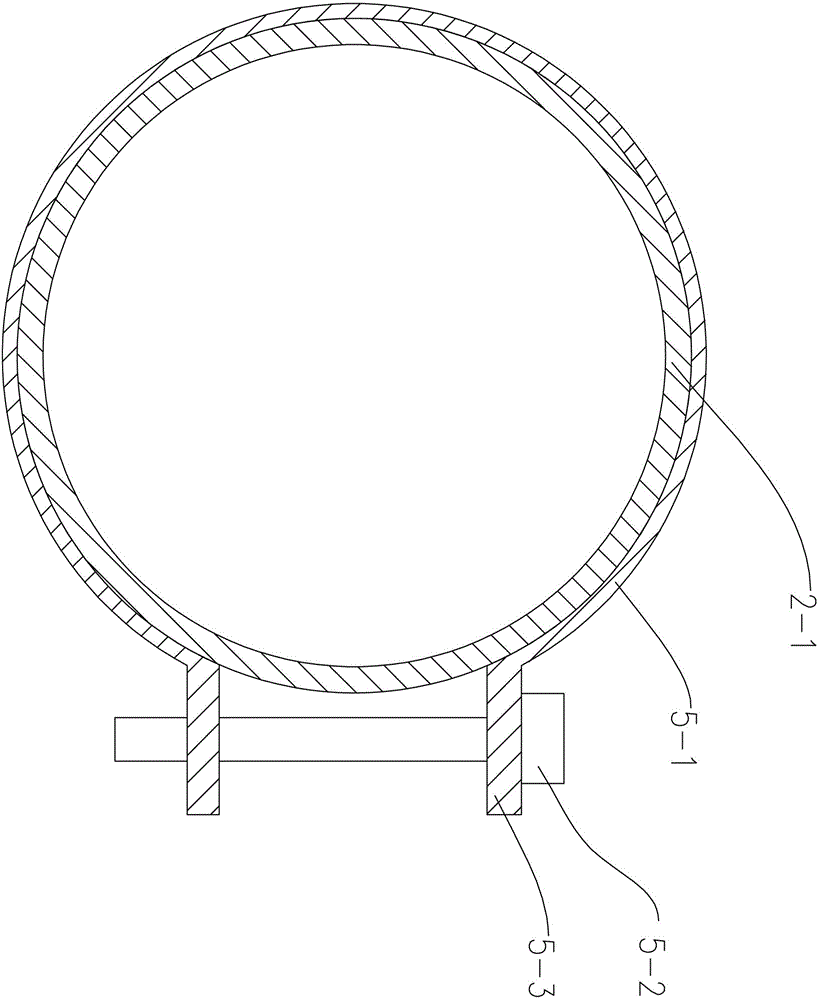
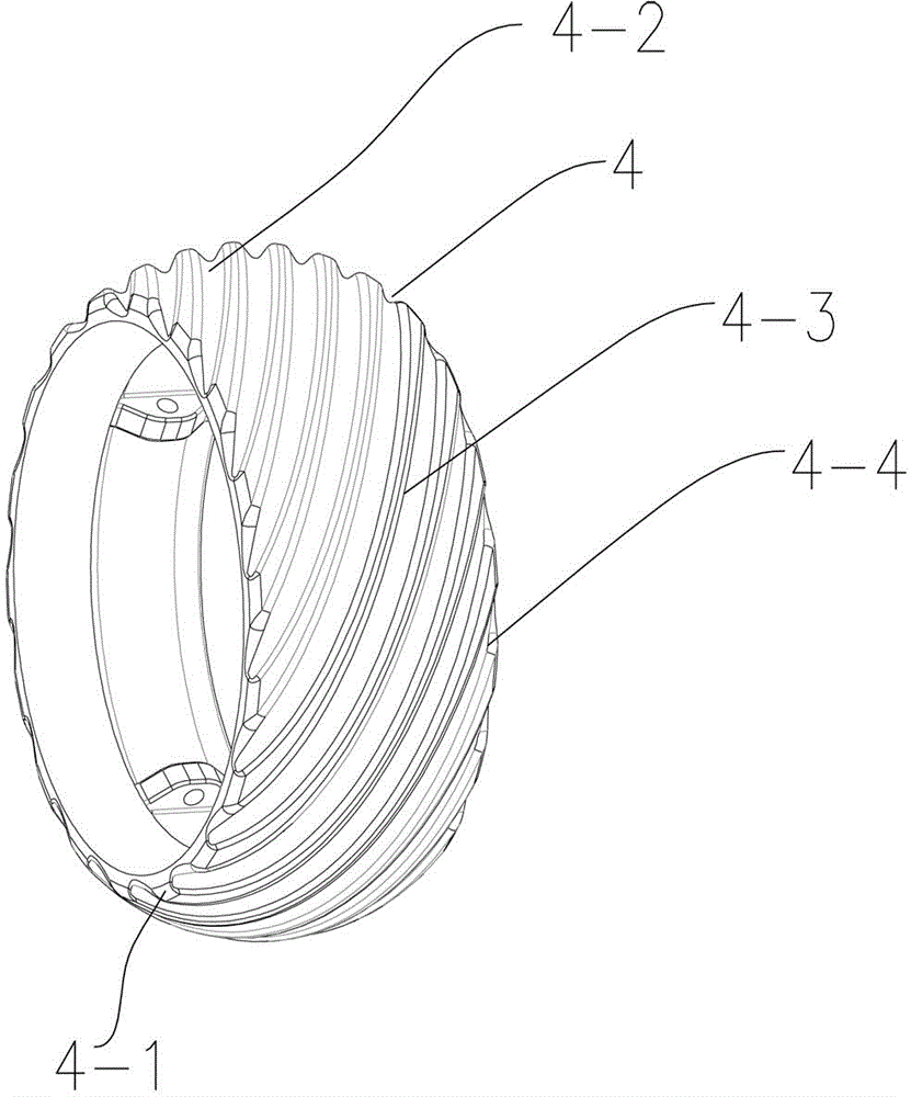
[0013] See attached figure 1 to attach image 3 As shown in this example, a vertical mill equipment for grinding ceramic raw materials described in this embodiment, wherein the tooth shape of the roller skin is an arc-shaped helical tooth, and the direction of rotation is right-handed. The vertical mill device includes a vertical mill shell 1. Material tank 2, grinding disc 3, grinding roller 4 and the scraper device 5 located at the lower end of the material tank 2, wherein the shell 5-1 of the scraper device 5 passes through two connecting plates 5-1 tightened by bolts 5-2 3 is tightly sleeved on the discharge port housing 2-1 at the lower end of the material tank 2, and the two connecting plates 5-3 are located at both ends of the housing 5-1. The lower end of the scraper device 5 is provided with scrapers 5-4 distributed in circular intervals along the bottom of the ho...


PUM


Abstract

The invention relates to a vertical mill device for milling ceramic raw materials. The vertical mill device comprises a vertical mill shell, a material tank, a milling disc, a milling roller, and a scrapping plate device positioned at the lower end of the material tank, wherein a shell body of the scrapping plate device is sleeved on a shell of a material outlet in the lower end of the material tank by two connection plates which are tensioned by bolts; the two connection plates are positioned at two ends of the shell body; scraping plates positioned at the bottom of the scrapping plate device are distributed in a circumference manner at intervals along the bottom of the shell body; the bottoms of the scrapping plates fit with an upwards raised tapered non-milling area in the center of the milling disc; a body of the milling roller is uniformly coated by a roller cover with inclined teeth, and the roller cover between two adjacent inclined teeth can form a particle channel. The vertical mill device has the advantages that the scrapping plate device is positioned at the lower end of the material discharging hole of the material tank, so that the problem that the ceramic raw materials are accumulated close to the center of the milling disc can be effectively solved; the inclined teeth are adopted for milling, so that the milling time of milled materials can be prolonged, and further the crushing efficiency is improved.

Description

technical field [0001] The invention relates to the technical field of ceramic raw material processing equipment, in particular to a vertical mill for grinding ceramic raw materials. Background technique [0002] In the existing vertical mill equipment for ceramic raw materials, the ceramic raw materials are directly dropped to the end surface of the rotating millstone below the hopper through the drop hopper, and the ceramic raw materials near the center of the millstone are difficult to move from the center of the millstone to the center of the millstone due to the small centrifugal force. Grinding area of ​​the grinding disc, resulting in the accumulation of ceramic raw materials in the center of the grinding disc, affecting the discharge of the hopper and the working efficiency of the equipment; and the rollers used in the existing vertical mill, the surface of the roller roller is close to a smooth smooth surface, which is in contact with the grinding disc When the grin...

Claims


Application Information

Patent Timeline
Patent Type & Authority Applications(China)
IPC IPC(8): B02C15/00
Inventor 梁海果严苏景梁志江陈伟强何标成严文记
Owner GUANGDONG BOFFIN MECHANICAL & ELECTRICAL CO LTD
Learn More