Wet scrubber having a compact demister that requires reduced energy demand

A wet scrubber and mist eliminator technology, which is applied to flushing wellbore, chemical instruments and methods, wellbore/well components, etc., can solve the problems of heavy mist eliminators, thick filter materials, difficult assembly, etc., and improve the purification effect. , small pressure loss, good wet-through effect

Active Publication Date: 2014-02-19
CFT GMBH
View PDF6 Cites 4 Cited by
  • Summary
  • Abstract
  • Description
  • Claims
  • Application Information

AI Technical Summary

Problems solved by technology

In this known deduster designed as a wet scrubber, it is disadvantageous that the demisters used are relatively heavy, ie have a high weight and can therefore only be assembled with a correspondingly large outlay.
In addition, assembly is made difficult by the fact that a relatively large design of the mist eliminator cannot be easily inserted into the scrubber housing in a cramped situation.
Furthermore, it is difficult and disadvantageous that the filter material (mainly steel wool) incorporated into the mist eliminator has a high energy demand due to its very thick arrangement and long flow paths

Method used


Image

  • Wet scrubber having a compact demister that requires reduced energy demand
  • Wet scrubber having a compact demister that requires reduced energy demand
  • Wet scrubber having a compact demister that requires reduced energy demand

Examples


Embodiment Construction

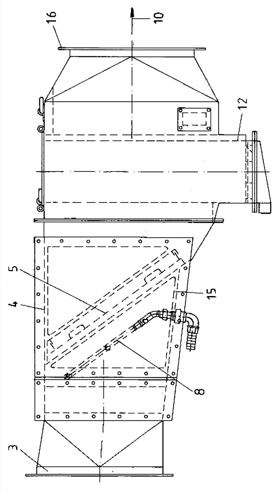
[0027] exist figure 1 In the wet scrubber 1 described in , the scrubber housing 2 is described as open in the area of ​​the demister 5 and closed in the remaining areas. Correspondingly, the demister sub-housing 4 with the demister 5 is connected to the air inlet connection 3, wherein the dust-laden air humidified by the humidification nozzles 6, 7 is then guided in the air direction to the droplets. In the catcher 11, its droplet catcher sub-housing 12 has an obliquely constructed bottom to which the sewage outlet 13 is connected.

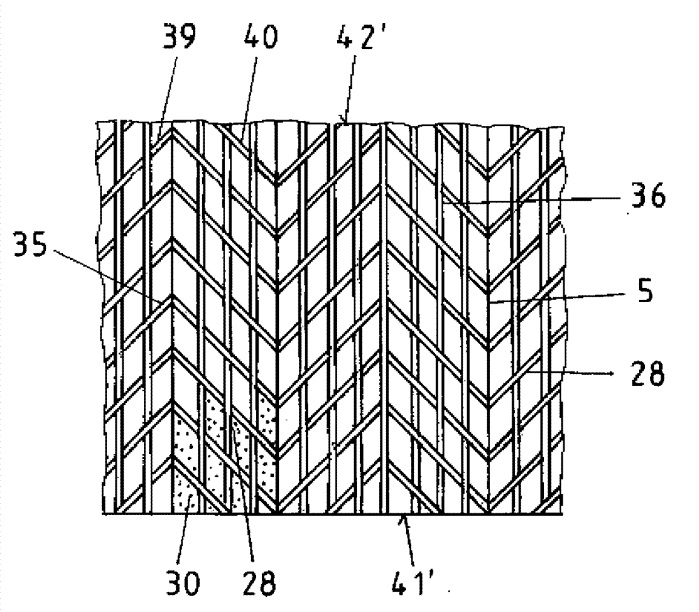
[0028] exist figure 1 The surface 26 of the filter element 25 of the mist eliminator 5 is not recognizable in the wavy configuration. This is more evident from the other figures. The humidification nozzles 6 , 7 aligned to the mating surface 26 ′ of the mist eliminator 5 are associated with the nozzle frame 8 and are arranged such that their nozzle openings 9 are directed onto the mist eliminator 5 . here in figure 1 It is further shown in th...


PUM


Abstract

A wet scrubber 1 with a low energy requirement, i.e. with reduced throughflow resistance has a demister 5, whose filter package 25 is shaped corrugated or folded. This makes a large surface available to ensure reliable soaking of the inflowing dust. Further advantages are a sloping bottom plate 15 in the demister part housing 4, specially positioned and designed moistening nozzles 6, 7 as well as above all a partitioning of the demister 5 into several complete packages 31, 33.

Description

technical field [0001] The invention relates to a wet scrubber (Nasswöscher) for use in underground mining and tunnel construction in the context of dust protection, with: a scrubber housing and associated ventilation (Lüfter); and A mist eliminator (Demister) with humidification nozzles; and a rear droplet catcher (Tropffänger) and a water tank with a valve-controlled fresh water inlet for circulating water. Background technique [0002] Such a wet scrubber is known in principle from the document DE 198 53 190 A1. In this wet scrubber, the necessary ventilation means are arranged between the inlet side and the outlet side before the mist eliminator and the droplet catcher. In order to ensure the necessary humidification or soaking of the dust, not only the mist eliminator, which is arranged to be suspended almost horizontally in the air flow, but also the fan wheel are provided with associated humidification nozzles. The fan wheel is therefore heavily loaded with dust and...

Claims


Application Information

Patent Timeline
IPC IPC(8): B01D47/06E21C35/22B01D46/52B01D46/00E21F5/20
CPCB01D46/0082E21F5/20B01D47/06B01D46/003B01D46/0079E21C7/08E21C35/223B01D46/521B01D46/69B01D46/79E21B21/013
Inventor R.博特C.豪博尔德
Owner CFT GMBH
Why Eureka
Try Eureka