
Control rod guide tube and fuel assembly

A technology for controlling rod guide tubes and fuel rods, which is applied in the field of reactor components, can solve problems such as limiting the CHF performance of fuel assemblies, and achieve the effects of improving rod dropping performance, shortening rod dropping time, and optimizing CHF performance.

Active Publication Date: 2014-02-19
CHINA NUCLEAR POWER TECH RES INST CO LTD +1
View PDF5 Cites 8 Cited by
  • Summary
  • Abstract
  • Description
  • Claims
  • Application Information

AI Technical Summary

Problems solved by technology

The control rods in the control rod guide tube will not generate heat because they do not participate in the chain reaction. The channel containing this control rod guide tube is a typical cold wall channel (also known as a cold wall cell). The cold fluid on the wall surface (that is, the outer wall of the control rod guide tube) will only flow from upstream to downstream along the cold wall surface, without fluid mixing with the hot fluid on the hot wall surface, so usually the control rod guide tube channel will become The short board of CHF performance of fuel assemblies limits the overall CHF performance of fuel assemblies

Method used


Image

  • Control rod guide tube and fuel assembly
  • Control rod guide tube and fuel assembly
  • Control rod guide tube and fuel assembly

Examples


Embodiment Construction

[0028] The preferred embodiments of the present invention will be described below in conjunction with the accompanying drawings.

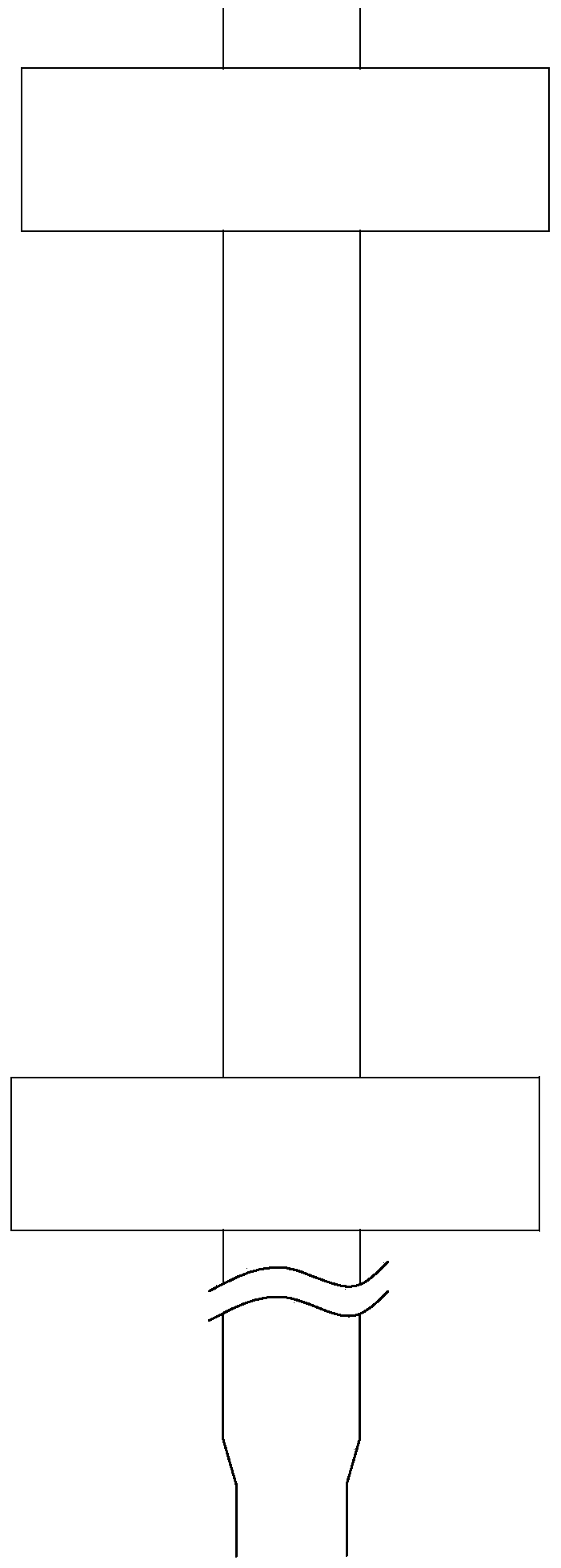
[0029] As shown in Figure 1, the fuel assembly 1 of the present invention includes an upper tube base 10, a lower tube base 11, a plurality of positioning grids 12, a control rod guide tube 13 and a fuel rod 14, and the control rod guide tube 13 and the fuel rod 14 Respectively inserted in a plurality of said positioning grids 12 parallel to each other, the uppermost said positioning grids 12 are matched and connected with said upper tube base 10, and the lowermost said positioning grids 12 are connected with said lower tube bases 11 matching connections. In practical applications, the plurality of spacer grids 12 may be an integrated structure. U in FIG. 1 is the flow direction of the coolant fluid in the fuel assembly 1 , that is, it flows from bottom to top.

[0030] refer to figure 2 As shown, the middle of the positioning grid 12 forms a g...


PUM


Abstract

The invention discloses a control rod guide tube, which is inserted in a spacer grid, the control rod guide tube has a hollow tubular structure, and several flow-disturbing openings through the sidewall of the control rod guide tube are provided with the control rod guide tube. According to the flow-disturbing openings on the sidewall of the control rod guide tube, fully mixing of cryogenic fluid on a cold wall surface and hot fluid on a hot wall surface in a cold wall lattice cell occupied by the control rod guide tube can be realized, fluid on the cold wall surface in the cold wall lattice cell can participate in channel heat exchange, thereby CHF performance of the control rod guide tube can be enhanced. The flow-disturbing opening can adjust the fluid resistance when the control rod drops, further the rod-dropping performance of the control rod under accident can be improved. Correspondingly, the invention also provides a fuel assembly possessing the control rod guide tube.

Description

technical field [0001] The invention relates to a reactor component, in particular to a fuel assembly control rod guide tube capable of enhancing critical heat flux density and rod drop performance. Background technique [0002] A certain number of fuel rods are arranged at certain intervals (such as: 15×15 or 17×17, etc.) and fixed into a bundle, which is called a reactor fuel assembly. Generally, it consists of an upper positioning grid, a lower positioning grid and 6-8 intermediate positioning grids), control rod guide tubes and fuel rods. Among them, the control rod guide tube is the load-bearing part of the fuel assembly framework, and its main functional requirements are: (1) Connect the upper and lower pipe sockets to form the component framework and provide continuity for the component structure; (2) Provide insertion for related component rods (3) provide a buffer for rapid rod drop shutdown in an accident, and prevent excessive impact force between the control rod...

Claims


Application Information

Patent Timeline
Patent Type & Authority Applications(China)
IPC IPC(8): G21C7/10G21C3/30G21C3/332
CPCY02E30/39Y02E30/30
Inventor 庞铮铮禹文池张玉相李伟才周跃民胡海翔
Owner CHINA NUCLEAR POWER TECH RES INST CO LTD
Learn More