Measuring method for maximum tensile and shearing force of spot-welded joint of friction stir welding

A friction stir, welding head technology, applied in the direction of using stable shear force to test material strength, using stable tension/pressure to test material strength, etc., can solve the problems of inaccurate measurement and influence of measurement results, etc.

Inactive Publication Date: 2014-02-19
HARBIN INST OF TECH
View PDF7 Cites 5 Cited by
  • Summary
  • Abstract
  • Description
  • Claims
  • Application Information

AI Technical Summary

Problems solved by technology

[0003] The purpose of the present invention is to solve the problem that the additional bending moment in the traditional tension-shear measurement method affects the measurement results of the maximum tension-shear force of the friction stir spot welded joint, resulting in inaccurate measurement, and proposes a method for measuring the maximum tension-shear force of the friction stir spot welded joint method of force

Method used


Image

  • Measuring method for maximum tensile and shearing force of spot-welded joint of friction stir welding
  • Measuring method for maximum tensile and shearing force of spot-welded joint of friction stir welding

Examples


specific Embodiment approach 1

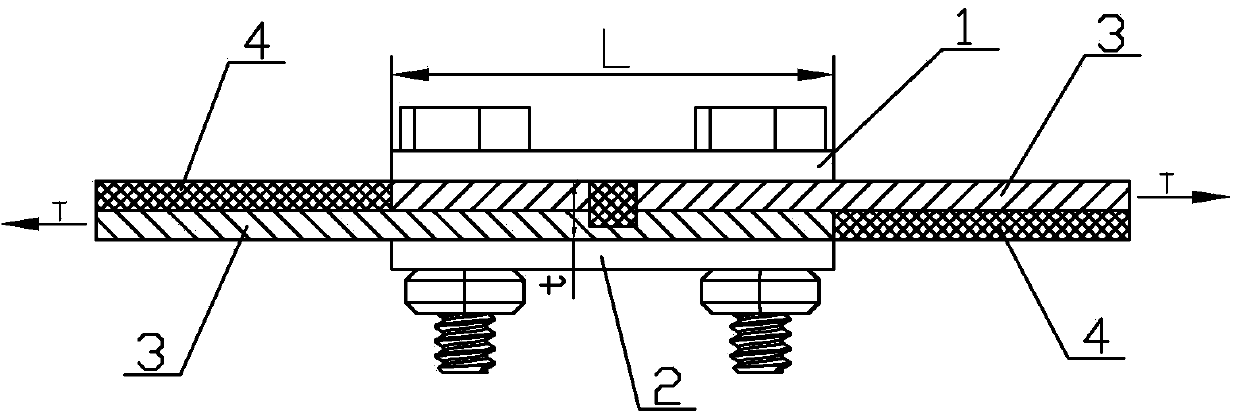
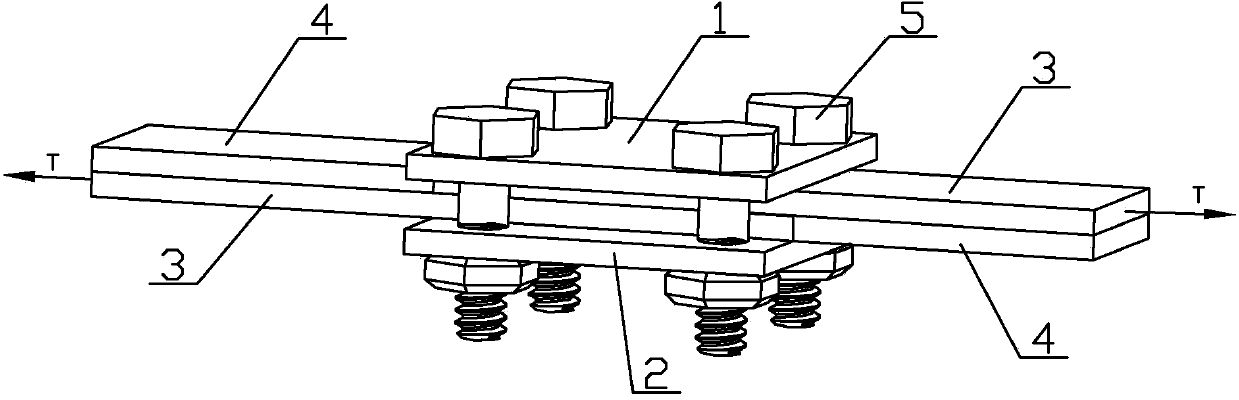
[0013] Specific implementation mode one: combine figure 1 and figure 2 Describe this implementation mode, this implementation mode is realized through the following steps:

[0014] Step 1. Making the jig: process the upper support side plate 1 and the lower support side plate 2, so that the lengths of the upper support side plate 1 and the lower support side plate 2 are equal, and the length L of the upper support side plate 1 is the tensile shear test 10 to 20 times the thickness t of the overlapping part of the piece 3, the upper supporting side plate 1 and the lower supporting side plate 2 are arranged in parallel up and down, and the gap is equal to the thickness of the overlapping part of the test piece 3 in tensile shear measurement, and the upper supporting side plate 1 and the lower supporting side plate 2 are arranged parallel to each other. The lower support side plate 2 is connected by bolts and nuts 5;

[0015] Step 2. Assemble the tensile-shear measurement spec...

specific Embodiment approach 2

[0017] Specific implementation mode two: combination figure 1 Describe this embodiment, this embodiment is that the length L of the upper support side plate 1 in step 1 is 12 times of the thickness t of the overlapping part of the tensile-shear measurement test piece 3 . In this way, the influence of the additional bending moment on the tensile-shear measurement specimen 3 can be neglected. Other steps are the same as in the first embodiment.

specific Embodiment approach 3

[0018] Specific implementation mode three: combination figure 1 Describe this embodiment, in this embodiment, the length L of the upper support side plate 1 in step 1 is 14 times the thickness t of the overlapping portion of the tensile-shear measurement specimen 3 . In this way, the influence of the additional bending moment on the tensile-shear measurement specimen 3 can be neglected. Other steps are the same as in the first embodiment.


PUM


Abstract

The invention relates to a measuring method for the tensile and shearing force of a spot-welded joint of friction stir welding and specifically provides a measuring method for the maximum tensile and shearing force of the spot-welded joint of friction stir welding to overcome the problem that measurement results of the maximum tensile and shearing force of a spot-welded joint of friction stir welding is not accurate in a traditional tensile and shearing force measurement method due to influence of additional bending moment. The method comprises the following steps: 1, fabrication of a fixture, wherein an upper support side plate and a lower support side plate are processed, and the length of the upper support side plate is 10 to 20 times thickness of the lap part of a test piece for tensile and shearing testing; 2, assembling of the test piece for tensile and shearing testing, wherein the test piece for tensile and shearing testing is arranged between the upper support side plate and the lower support side plate, and the non-lap parts at two sides of the test piece are respectively provided with a cushion block with thickness identical to the thickness of a sheet material to be welded; and 3, tensile and shearing testing, wherein the assembled test piece for tensile and shearing testing, the fixture and the cushion blocks are clamped on a tensile and shearing testing machine, tensile and shearing testing is carried out on the test piece for tensile and shearing testing at a loading speed of 0.5 to 1.5 mm / min, and a maximum tensile and shearing test load is recorded. The method provided by the invention is used for measuring the maximum tensile and shearing force of the spot-welded joint of friction stir welding.

Description

technical field [0001] The invention relates to a method for measuring the tensile shear force of a friction stir spot welding joint, in particular to a method for measuring the maximum tensile shear force of a friction stir spot welding joint. Background technique [0002] Friction stir spot welding is a new type of spot welding technology. Compared with traditional resistance spot welding, it has many advantages in welding low melting point metals, such as high welding quality, low production cost, and no environmental pollution. The most important performance index for evaluating friction stir spot welded joints is the maximum tensile shear force. However, due to the asymmetry of spot welded joints, the traditional tensile shear measurement method is to apply a large additional bending moment to the tensile shear measurement specimen to make it Bending-shear mixed fracture occurs, which affects the measurement of the maximum tensile shear force. Therefore, it is difficul...

Claims


Application Information

Patent Timeline
IPC IPC(8): G01N3/08G01N3/24
Inventor 刘会杰赵运强林喆陈诗璇
Owner HARBIN INST OF TECH
Why Eureka
Try Eureka