
Discharged flue gas self-heating technology of wet flue gas desulfurization and desulfuration purified flue gas self-heating device

A wet flue gas desulfurization and flue gas purification technology is applied in the field of wet flue gas desulfurization processes and devices, which can solve problems such as treating the symptoms rather than the root causes, and achieve the effects of extending the maintenance period, reducing the system resistance and reducing corrosion.

Inactive Publication Date: 2014-02-19
SHANGHAI UNIV
View PDF7 Cites 10 Cited by
  • Summary
  • Abstract
  • Description
  • Claims
  • Application Information

AI Technical Summary

Problems solved by technology

Although this can reduce resistance, it still has high anti-corrosion requirements for GGH equipment, and it is a temporary measure to treat the symptoms but not the root cause

Method used


Image

  • Discharged flue gas self-heating technology of wet flue gas desulfurization and desulfuration purified flue gas self-heating device

Examples


Embodiment 1

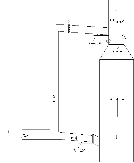
[0021] In this example, see figure 1 , a self-heating device for desulfurized clean flue gas. Outside the desulfurization tower Ⅰ, the original flue gas main flue is connected to one end of the independent bypass flue, and the other end of the bypass flue is connected to the direct discharge chimney II above the desulfurization tower Ⅰ Connected, that is, before the original flue gas main flue enters the desulfurization tower I, at the branch of the original flue gas main flue and the bypass flue, the original flue gas 1 begins to be divided into the flue gas 4 entering the desulfurization tower and the bypass flue gas 3 The flue gas 4 entering the desulfurization tower is sprayed and washed by desulfurization liquid in the desulfurization tower Ⅰ to form a clean flue gas 6 and rises into the straight chimney Ⅱ. The bypass flue gas 3 passes through the bypass flue gas outside the desulfurization tower Ⅰ. The flue gas is directly transported to the straight chimney II. In the s...

Embodiment 2

[0025] This embodiment is basically the same as Embodiment 1, especially in that:

[0026]Raw flue gas 1 from different equipment is collected in the main flue gas duct to form raw flue gas 1 with a relatively uniform temperature, and then divided into desulfurization tower flue gas 4 at the branch of the main flue gas flue and bypass flue And bypass flue gas 3 two parts. Since the temperature of the flue gas from different boiler equipment may be inconsistent, the self-heating device for the desulfurization net flue gas in this embodiment can collect the original flue gas from the induced draft fan of the coal-fired boiler and divide it into the flue gas entering the desulfurization tower and the flue gas bypassed. Partly, the temperature of the original flue gas is more uniform, the thermal vibration is reduced, and it is convenient to control the temperature of the exhausted flue gas through the temperature control method. In order to better ensure that the exhausted flue ...


PUM

PropertyMeasurementUnit
Thicknessaaaaaaaaaa

Abstract

The invention discloses a discharged flue gas self-heating technology of wet flue gas desulfurization. Original flue gas is divided into the thionizer entering flue gas and the bypass flue gas. After the thionizer entering flue gas is washed by spraying a doctor solution in a thionizer, purified flue gas is formed and enters a straight discharging chimney. The bypass flue gas is conveyed into the straight discharging chimney. In the straight discharging chimney, the purified flue gas and the bypass flue gas are fully mixed and then discharged into the atmosphere. Mixed flue gas meets the requirement for environment-protection discharging, meanwhile, the bypass flue gas exchanges heat with the purified flue gas, so that the temperature of the mixed flue gas is raised, and the discharging temperature of the mixed flue gas is controlled to reach more than 70 DEG C. The invention further discloses a desulfuration purified flue gas self-heating device. In order to overcome the defects of a GGH, heat flue gas is used for directly heating the purified flue gas, and the heat flue gas and the purified flue gas are mixed and then discharged. The technology is simple, resistance is small, the GGH does not need to be arranged, the maintenance workload of the device is small, and therefore the wet flue gas desulfurization device is more simple and more practical in technology and meets the requirement for long-time efficient operation.

Description

technical field [0001] The invention relates to a wet flue gas desulfurization process and device, in particular to a desulfurized clean flue gas heating process and device for the flue gas desulfurization process, which is applied in the technical fields of flue gas desulfurization and resources and environment. Background technique [0002] In order to control the sulfide concentration in coal-fired boiler emissions, for coal-fired and oil-fired units, it is necessary to consider adopting boiler tail gas desulfurization equipment, referred to as FGD system. There are many methods for flue gas desulfurization at the boiler tail, but wet flue gas desulfurization has been widely used because of its low cost, good desulfurization effect, and not limited by geographical environment. In order to increase the discharge temperature of the net flue gas after wet flue gas desulfurization, increase its diffusion range, and reduce the dew point corrosion of sulfuric acid, it is necess...

Claims


Application Information

Patent Timeline
IPC IPC(8): F23J15/00
Inventor 何仁初
Owner SHANGHAI UNIV
Learn More