A middle tank hydraulic crane

A hydraulic and crane technology, applied in the direction of cranes, etc., can solve the problems that flatbed trucks cannot pass, the width of the conveyor is limited, and the whole machine cannot be transported, so as to save workload, reduce the lateral size and facilitate transportation.

Active Publication Date: 2016-03-16
LIAONING XINFENG MINE IND GRP CO LTD
View PDF7 Cites 0 Cited by
  • Summary
  • Abstract
  • Description
  • Claims
  • Application Information

AI Technical Summary

Problems solved by technology

During the use of this equipment, there are the following disadvantages: 1. Due to the heavy weight of the front and rear conveyors and the middle tank, and limited by the width of the underground roadway, the width of the conveyor is limited, and the conveyor will be unstable during the lifting process; 2. Because the conveyor The size is too large and cannot be transported as a whole machine. It needs to be disassembled into parts and assembled underground, which is time-consuming, laborious, and inefficient. In addition, this equipment cannot allow the flatbed truck transporting the middle tank to pass through, so that every time it is transported to the middle tank, the flatbed truck must be pulled by the tractor immediately. The machine pulls the flatbed truck away, and then uses the flatbed truck to transport it to the middle slot of the next truck, which is less efficient

Method used


Image

  • A middle tank hydraulic crane
  • A middle tank hydraulic crane
  • A middle tank hydraulic crane

Examples


Embodiment Construction

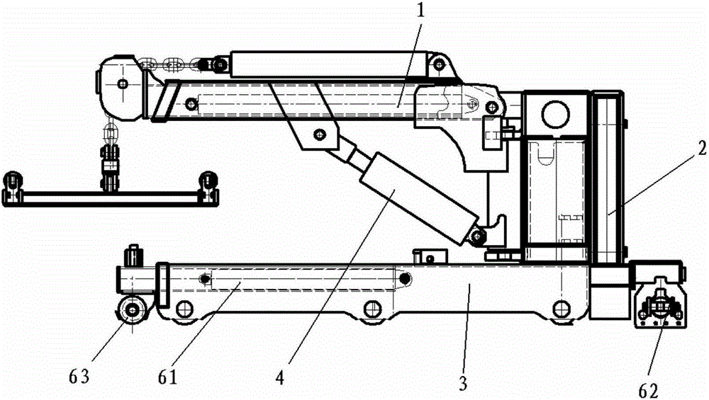
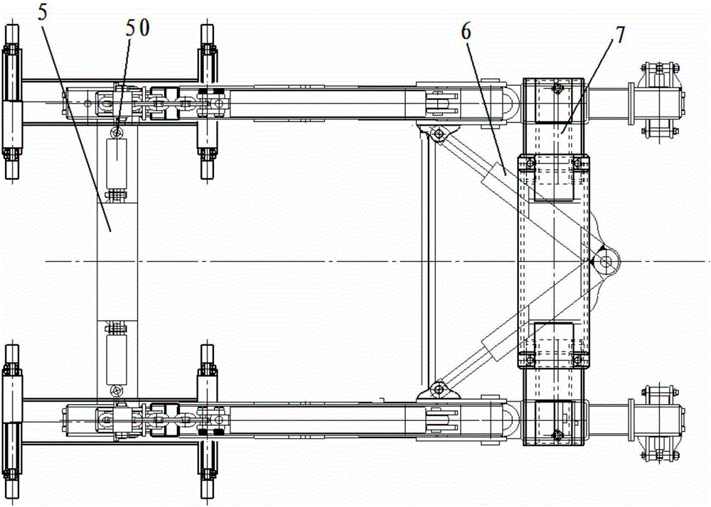
[0014] The present invention will be described in detail below in conjunction with the drawings, such Figure 1-Figure 3 As shown, the present invention includes a frame 3, a boom 1, a boom lifting cylinder 4, a boom rotating cylinder 6, etc. Support devices 2 are arranged on both sides of the frame 3; telescopic devices are arranged between the frames 3 on both sides, The telescopic device includes a frame telescopic cylinder 5 arranged at the bottom of the frame and a telescopic beam 7 arranged on the upper part of the frame.

[0015] The frame telescopic device includes two frame telescopic cylinders 5, the piston rod of the frame telescopic cylinder 5 is axially connected with the bottom of the frame 2, and the two frame telescopic cylinders 5 are axially connected.

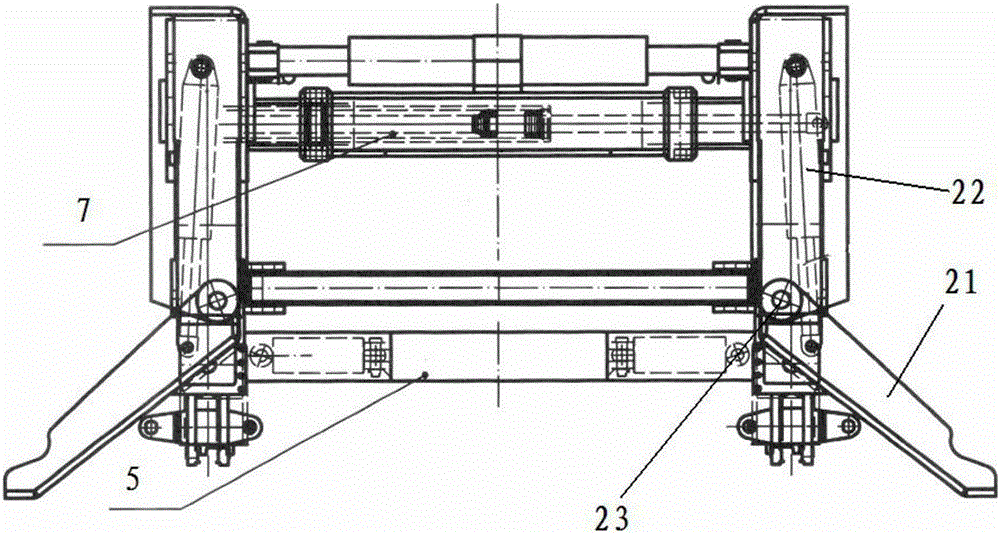
[0016] The supporting device 2 includes a supporting arm 21, which is axially connected to the piston rod of a supporting arm telescopic cylinder 22 arranged in the frame, and the supporting arm 21 can rotate arou...


PUM


Abstract

The invention discloses a hydraulic crane for a middle trough. The hydraulic crane comprises frames, a crane jib, a crane jib liftingoil cylinder, a crane jib rotating oil cylinder and the like, wherein a supporting device is arranged on the two sides of each frame, a telescopic device is arranged between the frames on the two sides and comprises a frame telescopic cylinder at the bottom of the frame and a telescopic beam at the upper part of the frame. The hydraulic crane for the middle trough has the advantages that the horizontal size of the hydraulic crane for the middle trough is greatly reduced, so that the hydraulic crane for the middle trough can be conveniently transported on the ground and underground, the dismounting procedure is canceled, and the production efficiency is greatly improved. As a supporting structure is added, the stability of the crane is guaranteed when the middle trough is lifted; in addition, as the frame telescopic cylinder is connected with the frames through pin shafts, the frame telescopic cylinder is conveniently dismounted when the crane works, so that the workload is greatly reduced, and the efficiency is improved by several times.

Description

Technical field [0001] The invention relates to the field of coal mine equipment, in particular to a central trough hydraulic crane. Background technique [0002] In the mining process of coal mines, a large number of middle troughs are needed to transport coal out. The installation of the central trough requires special equipment. Chinese Patent Application No. 2009100112701. The applicant is Liaoning Xinfeng Mining and Electric Equipment Manufacturing Co., Ltd., whose name is "Comprehensive Mining Equipment Hoisting Installation Vehicle", discloses a central trough hydraulic lifting equipment. The content is: a fully mechanized mining equipment hoisting installation vehicle, with track wheels under the frame, stepping devices at the front and rear ends, telescopic columns above the frame, and telescopic beams between the telescopic columns. The top of the hydraulic telescopic column is connected with a telescopic ceiling column, the front of the telescopic column is connected ...

Claims


Application Information

Patent Timeline
Patent Type & Authority Patents(China)
IPC IPC(8): B66C23/36B66C23/62
Inventor 张希望于代文史长林张晶史云龙刘明郑浩
Owner LIAONING XINFENG MINE IND GRP CO LTD
Why Eureka
Try Eureka