
Semi-submersible oil storage platform system for well drilling

A semi-submersible and drilling technology, applied to floating buildings and other directions, can solve the problems of low payload, high construction difficulty and cost, and poor mobility, so as to reduce the dependence on dynamic positioning, improve utilization rate and economy, and improve Effects on Stability and Sports Performance

Active Publication Date: 2014-02-19
DALIAN UNIV OF TECH
View PDF11 Cites 4 Cited by
  • Summary
  • Abstract
  • Description
  • Claims
  • Application Information

AI Technical Summary

Problems solved by technology

However, because the existing designs generally use large-diameter deep-draft cylinders or multiple deep-draft cylinders, their construction difficulty and cost are high, and their mobility is poor, the deck area is small, and the payload is low. It may also occur when encountering long-term swells. Nonlinear Coupling and Vortex Unsteady Motion
[0006] The semi-submersible platform has been developed to the sixth generation. It has good stability, large deck area, high payload, easy shifting, and low construction difficulty. Larger crude oil storage devices cannot be arranged on the platform, and generally the extracted crude oil can only be stored in its columns, so its oil storage capacity is low, and it is usually used as a deep-sea drilling platform

Method used


Image

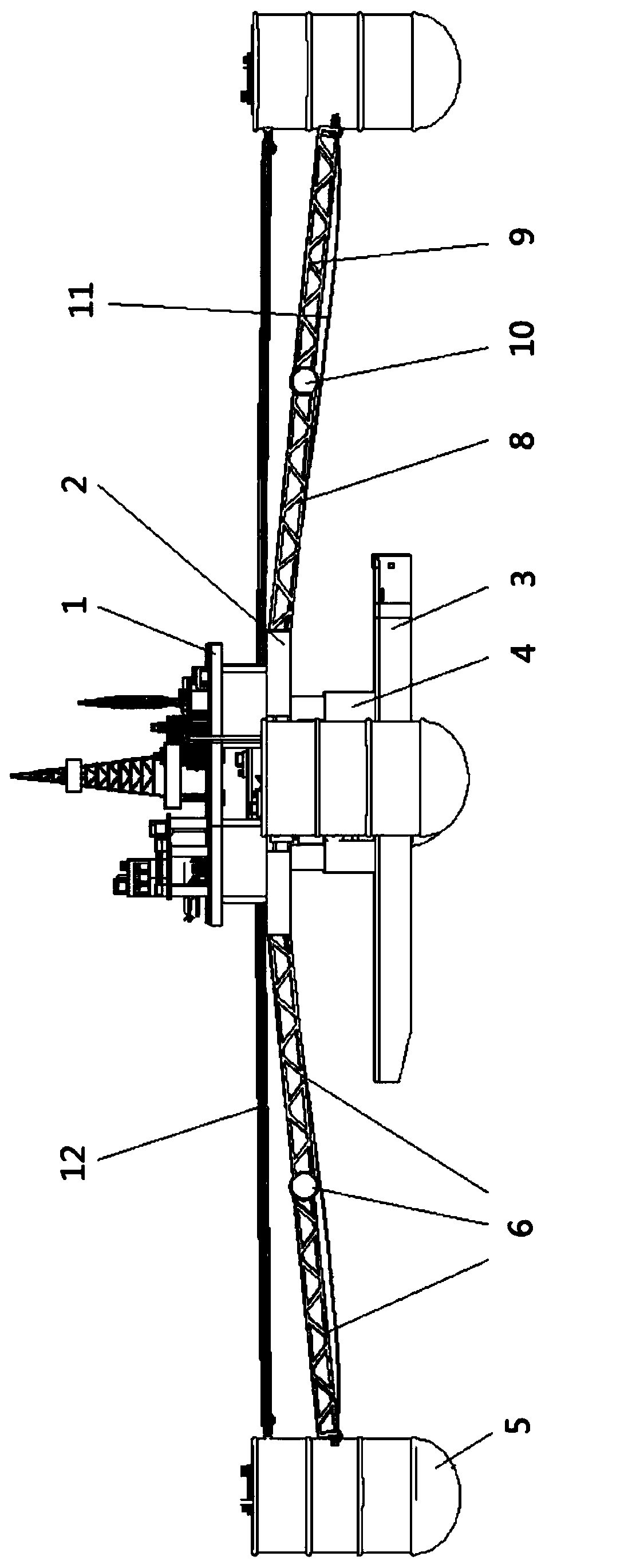
  • Semi-submersible oil storage platform system for well drilling
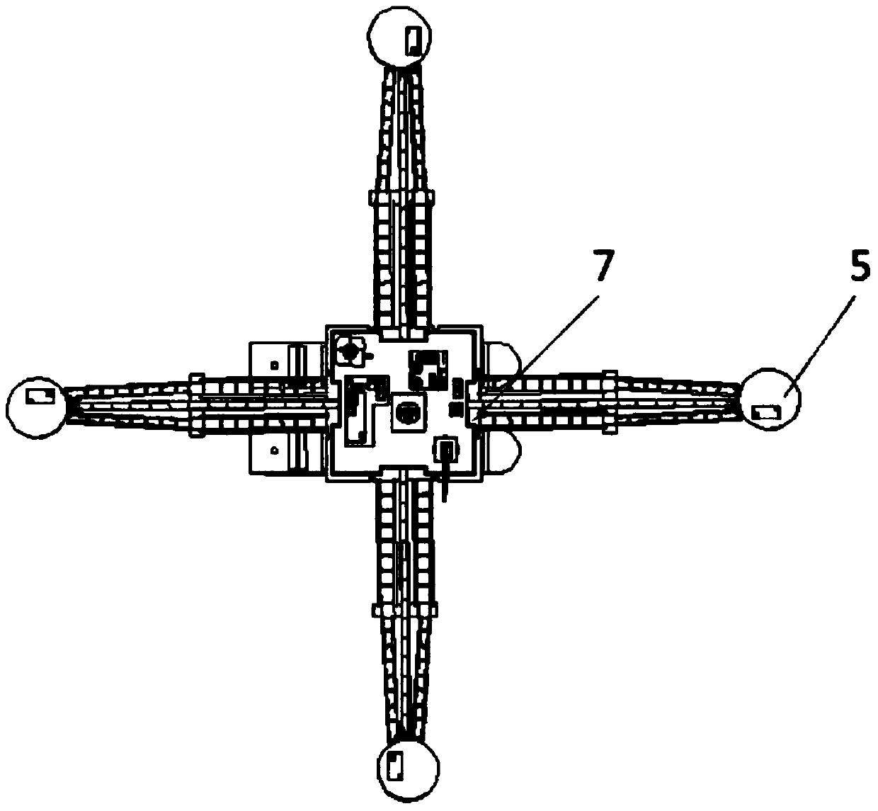
  • Semi-submersible oil storage platform system for well drilling
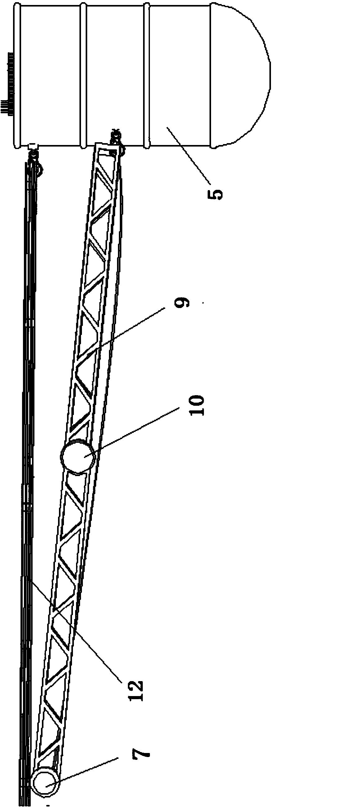
  • Semi-submersible oil storage platform system for well drilling

Examples


Embodiment Construction

[0027] In order to make the purpose, technical solutions and advantages of the embodiments of the present invention more clear, the technical solutions in the embodiments of the present invention are clearly and completely described below in conjunction with the drawings in the embodiments of the present invention:

[0028] Such as figure 1 — Figure 4 Shown: Example 1

[0029] A new semi-submersible drilling and oil storage platform system mainly includes a semi-submersible main platform, four floating sub-platforms, connecting arms and trestle structures connecting them. The main platform is mainly composed of a deck 1, a second deck 2, buoys 3, and columns 4. The four floating sub-platforms 5 are respectively located on the port side, starboard side, bow, and stern of the main platform. Each floating sub-platform is connected to the main platform through a truss connecting arm 6. The connecting arm 6 is perpendicular to the side of the middle part.

[0030] Each truss c...


PUM


Abstract

The invention discloses a semi-submersible oil storage platform system for well drilling. The semi-submersible oil storage platform system for well drilling comprises a semi-submersible main platform and a plurality of floating sub-platforms, wherein the floating sub-platforms are movably connected with the main platform through connecting arms, and motion of the floating sub-platforms is coupled with motion of the main platform. Due to the fact that the motion of the floating sub-platforms is coupled with the motion of the main platform in a deep sea environment with severe wind wave conditions, multi-freedom-degree motion of the main platform can be greatly reduced, the semi-submersible oil storage platform system for well drilling can have good adaptability, and the self-maintenance capacity of the semi-submersible oil storage platform system for well drilling under the storm condition is improved. Due to the fact that the floating sub-platforms in the four directions of the central main platform can play a role in storage of crude oil, the oil storage capacity of a semi-submersible oil storage platform for well drilling is greatly improved. Due to the fact that fuel compartments or fresh water tanks can also be arranged in the floating sub-platforms, the space of the main platform is effectively saved. Due to the fact that the floating sub-platforms are far away from the main platform, better operation safety is achieved.

Description

technical field [0001] The invention relates to a drilling and oil storage platform system, in particular to a modular group type semi-submersible platform suitable for drilling and oil production operations under severe deep sea conditions. Involved patent classification numbers: B63 Ships or other water craft; Ship-related equipment B63B Ships or other water craft; Marine equipment B63B35 / 00 Ships suitable for special purposes or similar floating structures B63B35 / 44 Floating structures, water warehouses , water drilling platforms or water workshops, such as those carrying oil-water separation equipment. Background technique [0002] In today's world where the energy demand is getting stronger and the energy supply is getting tighter and tighter, opening up wider energy supply channels has become the focus of the development of various countries. Among them, the development of offshore oil extraction technology is the fastest, and the deep sea and ultra- The deep sea cont...

Claims


Application Information

Patent Timeline
IPC IPC(8): B63B35/44
Inventor 郑向远于含戴昱坤周旭胡智焕王一凡
Owner DALIAN UNIV OF TECH
Learn More