
Column type hydraulic tappet

a hydraulic tappet and column type technology, applied in the direction of machines/engines, non-mechanical valves, valve arrangements, etc., can solve the problems of weak neck and head parts of the plunger, easy damage, etc., and achieve the effect of improving the fatigue strength of the plunger, simple and reliable structure, and increasing the oil storage capacity of the inner chamber

Active Publication Date: 2016-08-18
HANGZHOU XZB TECH
View PDF1 Cites 1 Cited by
  • Summary
  • Abstract
  • Description
  • Claims
  • Application Information

AI Technical Summary

Benefits of technology

The present invention is about a hydraulic tappet that has a single plunger with a simple and reliable structure. The invention increases the strength of the plunger by making the wall in the thin area of the unitary plunger thicker, while also increasing the oil storage capacity. This results in improved fatigue strength of the plunger.

Problems solved by technology

After research, the inventors found that the neck and head portions are weak areas of the plunger and are prone to damages due to fatigue.

Method used


Image

  • Column type hydraulic tappet
  • Column type hydraulic tappet
  • Column type hydraulic tappet

Examples


embodiment i

[0053]As shown in FIG. 4, a hydraulic tappet for a valve drive of an internal combustion engine comprises a cylindrical housing (2); an axial slidable plunger (1) installed in the housing. A high pressure chamber (10) for a hydraulic medium is located between a bottom face of plunger (1) and a bottom of housing (2), which can be sealed by an one-way check valve (3) located in a lower section of plunger (1). The housing (2) includes an external ring (circumferential) groove (13) on an external diameter for passing the hydraulic medium. An inner ring (circumferential) groove (8) for passing the hydraulic medium is located on an inner diameter of the housing, and one or more oil holes (7) are located between the two circumferential grooves for connecting the two circumferential grooves.

[0054]The plunger includes an indent wide circumferential groove (5), and one or more oil holes (6) are located in the indent wide circumferential groove (5). An inner circumferential groove (8) of the h...

embodiment ii

[0060]Unlike Embodiment I, as shown in FIG. 5, in the second embodiment, a smooth neck portion (4B) is located between the head portion (11) and the shaft portion.

embodiment iii

[0061]Unlike Embodiment I, as shown in FIG. 6, in the third embodiment, an orientation surface (15) of the plunger is a coalition of an arc surface and a conical surface, wherein the arc surface has a radius r of 0.3-0.8 mm and the conical surface has a conical (taper) angle α of 5°-15°.


PUM


Abstract

A column type hydraulic tappet includes a housing; a plunger correspondingly installed in the housing; and a high pressure chamber for a hydraulic medium formed between the bottom face of the plunger and the bottom of the housing and is sealed by a check valve opening toward the high pressure chamber. The housing includes an external circumferential groove on the outer diameter for passing the hydraulic medium and an inner circumferential groove on the inner diameter for passing the hydraulic medium. One or more housing oil holes are disposed between the outer circumferential groove and the inner circumferential groove. The plunger includes a sealed hemisphere head portion, a shaft portion and a body portion. An indent neck portion between the head and shaft portions of the plunger has a wall thickness 105%-120% of the wall thickness of the other portions of the plunger.

Description

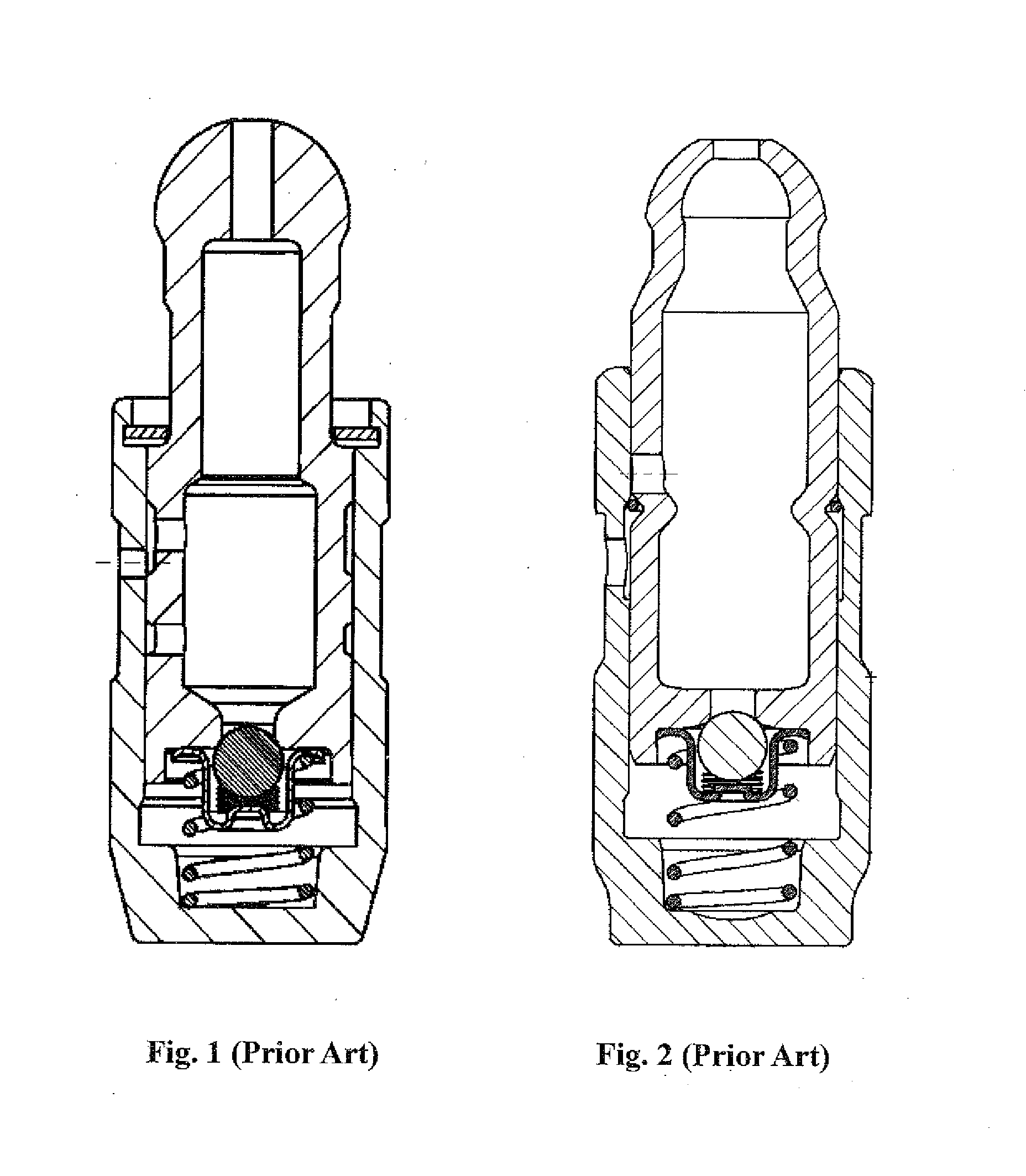
FIELD OF THE INVENTION[0001]The present invention relates to a column type hydraulic tappet.BACKGROUND[0002]Hydraulic tappet (hydraulic valve lifter) can be used to automatically compensate for valve lash (valve clearance), to reduce shock and noise of valve train (valve gear), to reduce abrasion or wear of working surfaces of the valve train, and to improve emission and combustion efficiency of thane engine.[0003]The structures of existing hydraulic tappets include several different types as disclosed in the prior art.[0004]As shown in FIG. 1, Chinese patent publication CN201593451U discloses a hydraulic support element, wherein the plunger is machined after cold heading. The machining processes are complicated, and these processes take time and efforts. After the process cutting off material to make the neck portion of the plunger, the metal flow line of the material is cut off. The thickness of the neck is smaller than those of other portions. The sizes of the two cross-sections ...

Claims


Application Information

Patent Timeline
Patent Type & Authority Applications(United States)
IPC IPC(8): F15B15/14F01L9/02F15B1/26F01L1/14F01L9/10
CPCF01L1/24F01L1/2405F01L2820/01F15B15/1447F01L9/02F15B1/26F15B15/1428F01L1/146F01L2303/00F01L9/10
Inventor XU, NA
Owner HANGZHOU XZB TECH
Learn More