
Automobile brake pedal structure with adjustable lever ratio

A technology of brake pedal and lever ratio, which is applied in the direction of foot-operated starting devices, etc., can solve the problems of wasting matching time, excellent pedal feeling, and impossibility of realization

Inactive Publication Date: 2014-02-19
FUZHUO AUTOMOBILE INTERIOR ANHUI
View PDF8 Cites 2 Cited by
  • Summary
  • Abstract
  • Description
  • Claims
  • Application Information

AI Technical Summary

Problems solved by technology

[0003] At present, in the braking performance matching test, the pedal with a fixed lever ratio i=L1 / L2 is installed on the car for the test, and the pedal feel is evaluated. If the pedal feel is poor, it is necessary to replace the pedal with a different lever ratio and try again. Wastes matching time and does not achieve optimal pedal feel

Method used


Image

  • Automobile brake pedal structure with adjustable lever ratio
  • Automobile brake pedal structure with adjustable lever ratio

Examples


Embodiment Construction

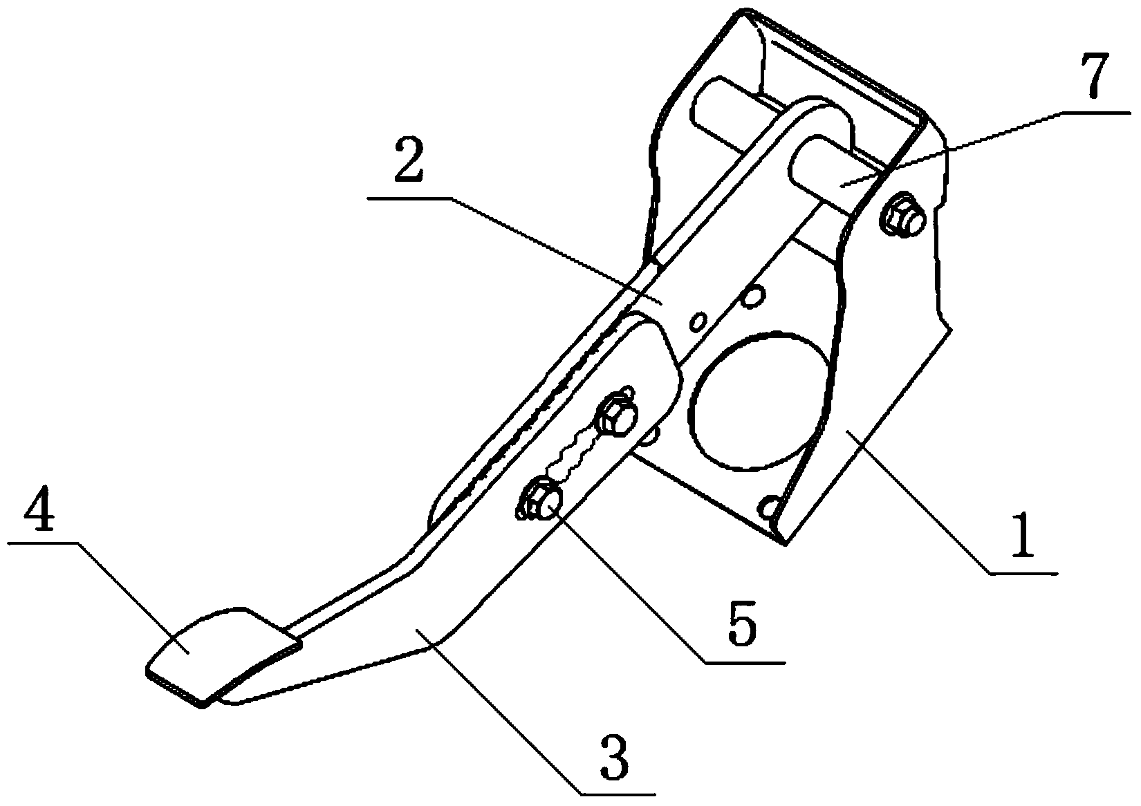
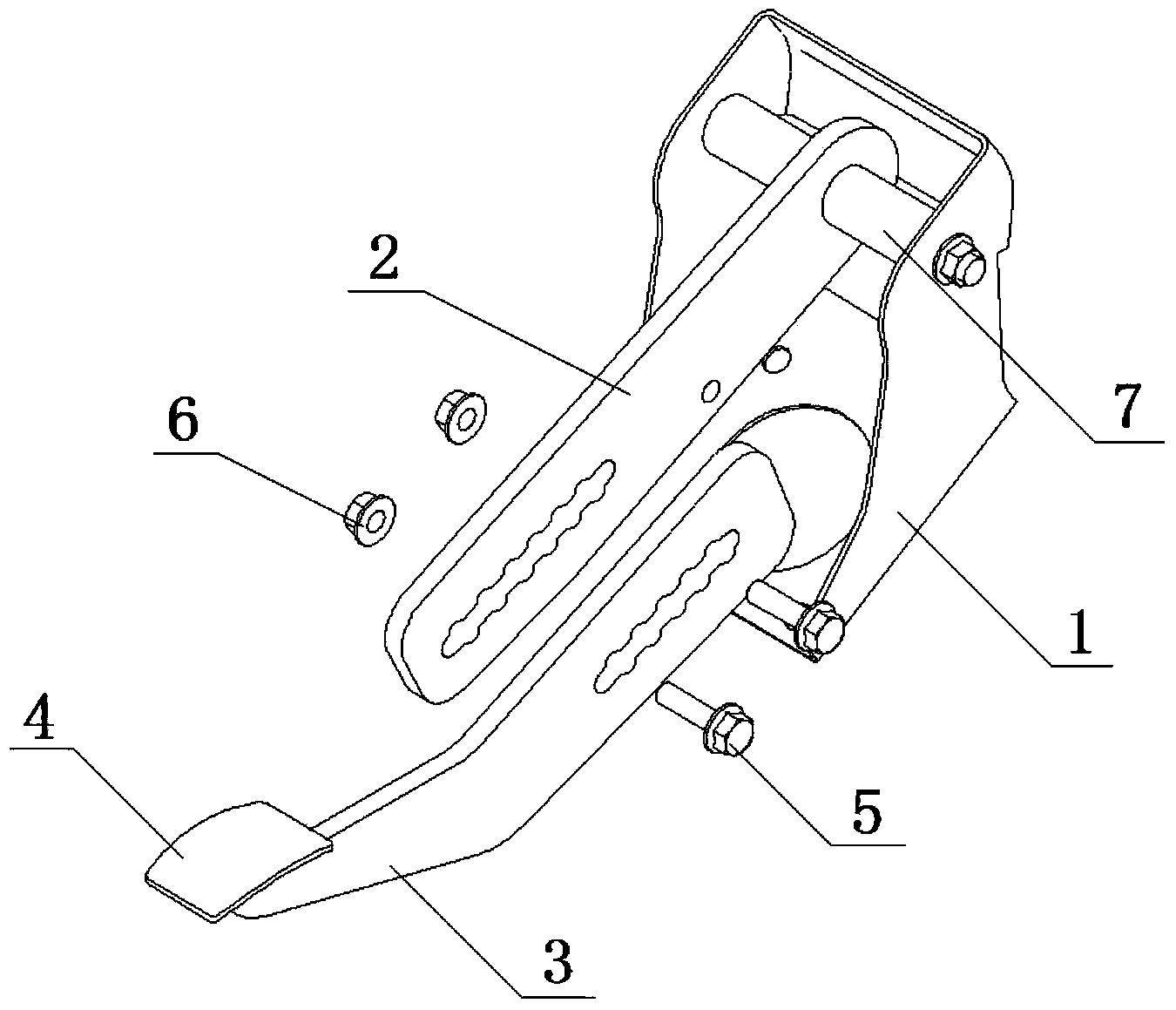
[0013] figure 1 It is a structural schematic diagram of the present invention, figure 2 for figure 1 Top view of the structure shown. Depend on Figure 1-Figure 2 Combining the shown structures, it can be seen that the brake pedal structure with adjustable leverage ratio for automobiles includes a pedal bracket 1 installed on the vehicle body, one end of the first pedal arm 2 is installed on the pedal bracket 1 through a pin shaft 7, and the other end A second pedal arm 3 is installed, and a pedal 4 is installed on the end of the second pedal arm 3. The first pedal arm 2 and the second pedal arm 3 are provided with elongated through holes. The first pedal arm 2 and the second pedal arm 3 are fixed together through the elongated through holes on the first pedal arm 2 and the second pedal arm 3 through bolts 5, there are at least two bolts 5, and the two ends of the elongated through holes are respectively Install at least one bolt 5.

[0014] The two long sides of the elo...


PUM


Abstract

The invention discloses an automobile brake pedal structure with an adjustable lever ratio. The automobile brake pedal structure with the adjustable lever ratio comprises a pedal support installed on an automobile body. One end of a first pedal arm is installed on the pedal support and the other end of the first pedal arm is provided with a second pedal arm. The end portion of the second pedal arm is provided with a pedal. The first pedal arm and the second pedal arm are respectively provided with a long-strip-shaped through hole. The first pedal arm and the second pedal arm are fixed together in the mode that bolts penetrate through the long-strip-shaped through holes of the first pedal arm and the second pedal arm. The two long edges of each long-strip-shaped through hole are respectively and symmetrically provided with a plurality of arc grooves. The bolts are installed in the arc grooves. The end portions of the bolts are locked through nuts. By the adoption of the automobile brake pedal structure with the adjustable lever ratio, it is guaranteed that in the process of use of the pedal, the lever ratio of the pedal can be adjusted by a driver according to the different requirements for the pedal feeling of the driver, pedal parameters convenient to utilize can be provided for performance matching of a brake system, and therefore the brake system with a good pedal feeling can be designed.

Description

technical field [0001] The invention relates to a brake pedal mechanism, in particular to a brake pedal structure with adjustable lever ratio for automobiles. Background technique [0002] The braking of the car is realized by stepping on the brake pedal, and the pedal produces a certain reaction force on the foot at the same time. As the requirements for driving comfort increase, the requirements for pedal feel when braking are also constantly increasing. [0003] At present, in the braking performance matching test, the pedal with a fixed lever ratio i=L1 / L2 is installed on the car for the test, and the pedal feel is evaluated. If the pedal feel is poor, it is necessary to replace the pedal with a different lever ratio and try again. It wastes matching time and fails to achieve optimal pedal feel. Contents of the invention [0004] The technical problem to be solved by the present invention is to provide a brake pedal structure with adjustable lever ratio for automobil...

Claims


Application Information

Patent Timeline
Patent Type & Authority Applications(China)
IPC IPC(8): B60T7/06
Inventor 童劭瑾苏荣敏程房江余庆耕
Owner FUZHUO AUTOMOBILE INTERIOR ANHUI
Learn More