Heat sink and electronic apparatus provided with heat sink

A technology for radiators and controllers, which is applied in the construction of electrical equipment components, instruments, circuits, etc. It can solve the problems of impossible elimination of failure rate, narrow cooling control range, difficulty in suppressing heat generation, etc.

Inactive Publication Date: 2014-02-12
FUJITSU LTD
View PDF14 Cites 8 Cited by
  • Summary
  • Abstract
  • Description
  • Claims
  • Application Information

AI Technical Summary

Problems solved by technology

This is because conventional heat sinks have high thermal resistance and narrow cooling control range, so temperature control of semiconductor packages has become impossible
In addition, if temperature control of the semiconductor package is impossible, it is difficult to suppress self-heating until reaching the device destruction temperature at the time of the temperature test of the semiconductor package
Further, if high-speed temperature control is not possible, temperature test conditions (temperature, voltage, etc.) may be easy to run the test, but the problem is that it is impossible to eliminate the failure rate in the later steps
The reason why it is not possible to eliminate the failure rate in the later steps is that the temperature test cannot be performed under "system test conditions"

Method used


Image

  • Heat sink and electronic apparatus provided with heat sink
  • Heat sink and electronic apparatus provided with heat sink
  • Heat sink and electronic apparatus provided with heat sink

Examples


Embodiment Construction

[0024] Hereinafter, embodiments of the present application will be explained based on specific examples using the drawings.

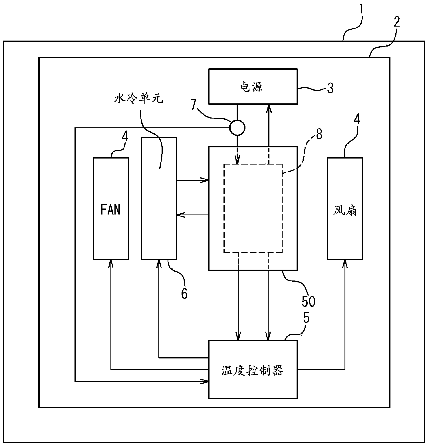
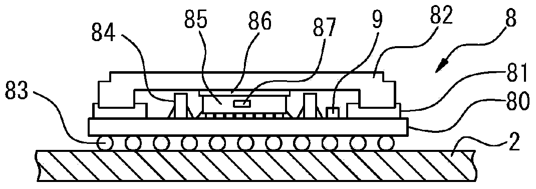
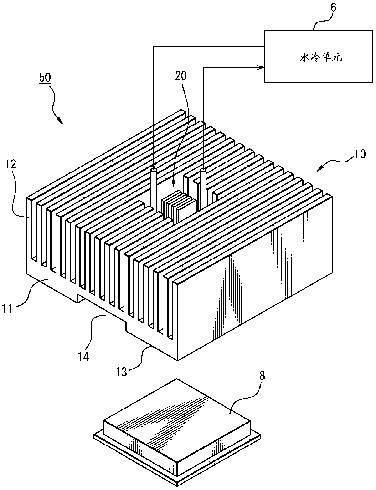
[0025] FIG. 1 is a layout diagram showing the layout of circuit elements mounted on a unit 2 mounted on an electronic device 1 and a heat sink 50 pair forming one of the circuit elements of a heat generating member 8. Allow to cool. The heat generating member 8 is, for example, a semiconductor package 8 . On the unit 2 , a power supply 3 for supplying electric power to the semiconductor package 8 and a fan 4 for cooling the semiconductor package 8 are provided. The radiator 50 of the present application comprises a fluid path through which the cooling water circulates, so that the unit 2 is provided with a water cooling unit 6 .

[0026] The water cooling unit 6 , the power supply 3 and the temperature controller 5 can also be arranged outside the unit 2 . In addition, the unit 2 may be provided with a temperature controller 5 controlling the fan 4 a...


PUM


Abstract

A heat sink for cooling a heat generating member, provided with a first cooling part which cools the peripheral edge part of the heat generating member and a second cooling part which cools the center part of the neat generating member, the first cooling part is equipped with a first base member having first fins on the top surface thereof and a recess at the bottom surface thereof, the second cooling part is equipped with a second base member which can be accommodated in the recess, a slide member which is provided on the top surface of the second base member and which is inserted in a through hole which is provided in the recess, second fins which are provided on the free end of the slide member, and a cooling water passage which is provided inside of the second base member and which is supplied with cooling water.

Description

[0001] Cross References to Related Applications [0002] This application claims priority from Japanese Patent Application No. 2012-172883 filed on Aug. 3, 2012, and the entire disclosure thereof is incorporated herein by reference. technical field [0003] The present application relates to a heat sink placed on a heating element to prevent the temperature of the heating element from rising, and the present application relates to an electronic device provided with the heat sink. Background technique [0004] In the past, a semiconductor provided inside an electronic device, especially a CPU package generates heat during operation and becomes high in temperature, so a heat sink is attached to prevent an excessive rise in temperature. Heretofore, heat sinks have been formed from aluminum and other metallic materials with good thermal conductivity. A heat sink comprising a base member placed on a heat generating member, on which a large number of fins protruding at predetermi...

Claims


Application Information

Patent Timeline
Patent Type & Authority Applications(China)
IPC IPC(8): H05K7/20G06F1/20
CPCH05K7/20281H05K7/20209H01L23/40H01L23/4006H01L23/427H01L23/467H01L23/473H01L2023/4056H01L2924/0002H01L2924/00H01L23/367
Inventor 冈本智美山田博
Owner FUJITSU LTD
Why Eureka
Try Eureka