A special electron gun for electron beam bombardment furnace
What is Al technical title?
Al technical title is built by PatSnap Al team. It summarizes the technical point description of the patent document.
A technology of electron beam bombardment and electron gun, which is applied in the direction of circuits, discharge tubes, electrical components, etc., can solve the problems of reducing the life of the cathode, decreasing the beam flux rate, and affecting the life of the electron gun, so as to achieve the effect of reducing life and improving stability
Active Publication Date: 2016-02-24
GUILIN UNIV OF ELECTRONIC TECH
View PDF6 Cites 0 Cited by
Summary
Abstract
Description
Claims
Application Information
AI Technical Summary
This helps you quickly interpret patents by identifying the three key elements:
Problems solved by technology
Method used
Benefits of technology
Problems solved by technology
The disadvantage of this electron gun is that the control of the electron beam current can only control its average value, and the time constant is relatively large. When the electron beam is transient, it may cause the beam flux rate of the electron gun to drop and affect the life of the electron gun.
If the cathode and beamforming electrodes are separated, the grid bias voltage E is changed b The method of changing the effective emission area of the cathode to control the electron beam current can partially improve the transient beam flux rate of the electron beam, but the grid bias voltage E b Reducing the emission capability of the cathode will increase the operating temperature of the cathode, thereby reducing the life of the cathode
Method used
Image
Click on the blue label to locate the original text in one second.
Reading with bidirectional positioning of images and text.
Examples
Embodiment Construction
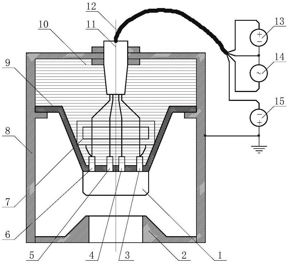
[0011] A special electron gun for electron beam bombardment furnace, such as figure 1 As shown, it mainly consists of an electron gun housing 8, and a filament, a cathode and a focusing electrode assembly 1, an anode 2, a focusing electrode 3, a filament head end electrode 4, a filament end electrode 5, and a cathode electrode arranged in the electron gun housing 8. 6. Insulation assembly 9, insulation cooling oil 10 and high voltage cable outlet 11. The first electrode 4 of the filament and the end electrode 5 of the filament are led out through the high-voltage cable lead-out head 11 fixed on the electron gun shell 8 and connected to the two poles of the filament power supply 14 through the high-voltage cable 12 respectively. The focusing electrode 3 and the cathode electrode 6 are also led out through the above-mentioned high-voltage cable lead-out head 11 and connected to the negative pole of the accelerating power supply 15 and the positive pole of the bombardment power s...
PUM
Abstract
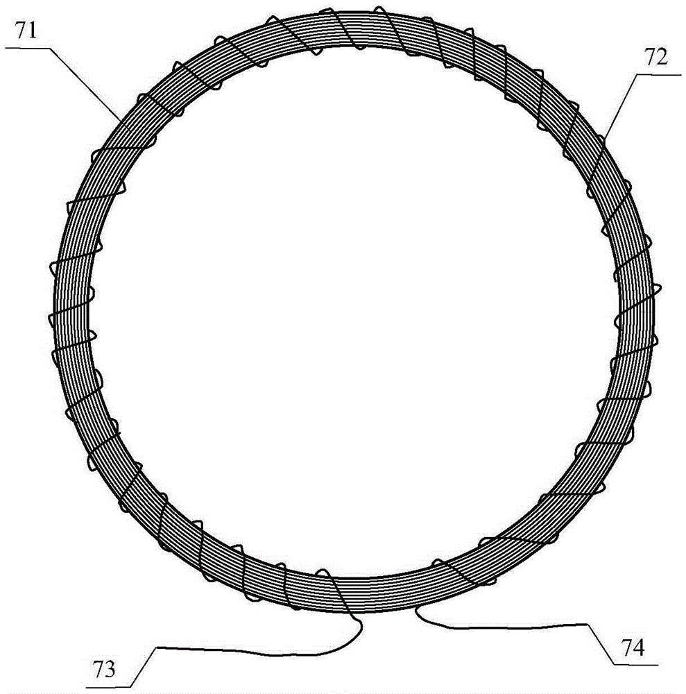
The invention discloses an electronic gun special for an electron beam bombardment furnace. The electronic gun is mainly composed of an electronic gun shell, lamp wires, a cathode, a beam-forming electrode assembly, an anode, a beam-forming electrode, a lamp wire head end electrode, a lamp wire tail end electrode, a cathode electrode, an electric reactor, an insulation assembly, insulation coolant oil and a high-voltage cable leading-out head, wherein the lamp wires, the cathode, the beam-forming electrode assembly, the anode, the beam-forming electrode, the lamp wire head end electrode, the lamp wire tail end electrode, the cathode electrode, the electric reactor, the insulation assembly, the insulation coolant oil and the high-voltage cable leading-out head are arranged in the electronic gun shell. The electric reactor which is additionally arranged is composed of an iron core and a winding wound on the iron core. The electric reactor is immersed in the insulation coolant oil. The head end of the winding of the electric reactor is connected with the beam-forming electrode, and the tail end of the winding of the electric reactor is connected with the cathode electrode. The electronic gun can restrain the transition of an electron beam, and therefore the beam passing rate of the electronic gun is improved.
Description
technical field [0001] The invention relates to the field of electron beam processing equipment, in particular to an electron gun dedicated to an electron beam bombardment furnace. Background technique [0002] The electron gun of the electron beam bombardment furnace usually adopts an axisymmetric Pierce electron gun structure, and the electron beam emitted by the cathode is restricted by the temperature-limited state and the space-charge-limited state. The saturated electron beam current density emitted by the cathode in the temperature-limited state is given by the formula decision, where i s is the saturated electron beam current density emitted by the cathode, A 0 is the Richardson constant, T is the thermodynamic temperature of the cathode, k is the Boltzmann constant, is the work function of the cathode material. In the state of space charge limitation, at a certain cathode temperature, the electron beam current density emitted by the cathode is given by the for...
Claims
Application Information
Patent Timeline
Application Date:The date an application was filed.
Publication Date:The date a patent or application was officially published.
First Publication Date:The earliest publication date of a patent with the same application number.
Issue Date:Publication date of the patent grant document.
PCT Entry Date:The Entry date of PCT National Phase.
Estimated Expiry Date:The statutory expiry date of a patent right according to the Patent Law, and it is the longest term of protection that the patent right can achieve without the termination of the patent right due to other reasons(Term extension factor has been taken into account ).
Invalid Date:Actual expiry date is based on effective date or publication date of legal transaction data of invalid patent.