
Pneumatic gate valve

A technology of gates and gates, applied in the field of pneumatic gates, which can solve problems such as premature reimbursement, improper closing of gates, and shortened life of pneumatic gates, so as to reduce energy consumption, reduce power generation costs, and reduce maintenance difficulty and cost Effect

Inactive Publication Date: 2014-02-12
宜都中起重工机械有限公司
View PDF0 Cites 2 Cited by
  • Summary
  • Abstract
  • Description
  • Claims
  • Application Information

AI Technical Summary

Problems solved by technology

For example, slag is easy to accumulate at the bottom of the pneumatic gate, causing the gate to not close properly, and the opening speed is slow, causing serious wear and tear on the outlet end of the pneumatic gate. Early reimbursement
In addition, the airtightness of the pneumatic gate is the most important technical performance index of the gate. The sealing performance of the contact between the gate plate and the sealing surface of the gate shell will affect the ability of the gate to cut off the medium, and the existing pneumatic gates are not tightly sealed. The problem

Method used


Image

  • Pneumatic gate valve
  • Pneumatic gate valve
  • Pneumatic gate valve

Examples


Embodiment Construction

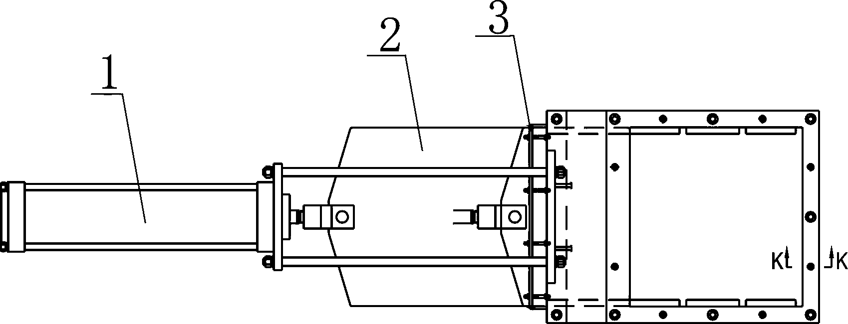
[0016] Such as Figure 1~Figure 4 As shown, a pneumatic gate includes a cylinder group 1 and a gate plate 2. The housing of the pneumatic gate includes: an upper half seat 6 and a lower half seat 4, the upper half seat 6 is connected with the lower half seat 4, and the upper half seat 6 is connected with the lower half seat 4. The end of the housing formed by the half seat 6 and the lower half seat 4 is square, and the upper half seat 6 and the lower half seat 4 are respectively connected to the sealing gland 3 by studs 8 .

[0017] The push-pull force generated by the cylinder group 1 makes the gate plate 2 move back and forth to realize the closing and opening of the pneumatic gate.

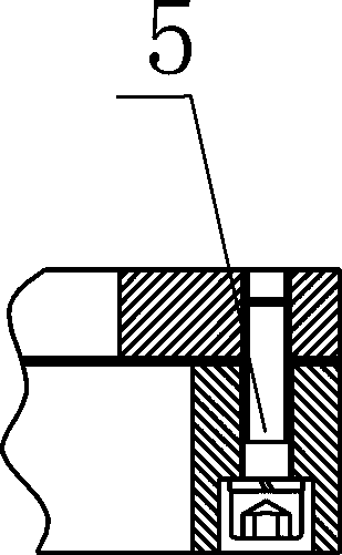
[0018] The upper half seat 6 and the lower half seat 4 are fixedly connected by hexagon socket head cap screws 5 .

[0019] The upper half seat 6 is connected to the lower half seat 4 through a square connection flange. Oil-impregnated asbestos 7 is provided at the positions where the upper h...


PUM


Abstract

The invention relates to a pneumatic gate valve which comprises a cylinder group and a gate plate; a shell of the pneumatic gate valve comprises an upper half seat and a lower half seat which are connected with each other; the tail end of the shell formed by the upper half seat and the lower half seat is in a square shape; the upper half seat and the lower half seat are respectively connected with a sealing gland by a double-end stud. The sealing performance of the pneumatic gate valve is guaranteed, the service life of the pneumatic gate valve is prolonged, and the safe operation rate of power plant equipment can be increased.

Description

technical field [0001] The invention relates to a pneumatic gate, which is suitable for controlling flow changes and cutting off quickly in industries such as metallurgy, mining, building materials, grain, and chemical industry. Background technique [0002] In the ash removal system of thermal power plants, there are some problems in the use of pneumatic gates. For example, slag is easy to accumulate at the bottom of the pneumatic gate, causing the gate to not close properly, and the opening speed is slow, causing serious wear and tear on the outlet end of the pneumatic gate. Early reimbursement. In addition, the airtightness of the pneumatic gate is the most important technical performance index of the gate. The sealing performance of the contact between the gate plate and the sealing surface of the gate shell will affect the ability of the gate to cut off the medium, and the existing pneumatic gates are not tightly sealed. The problem. Contents of the invention [00...

Claims


Application Information

Patent Timeline
IPC IPC(8): F16K27/04F16K3/18
CPCF16K27/04F16K3/18
Inventor 黄文静王海涛吴华峰谭宏伟薛玉莹
Owner 宜都中起重工机械有限公司
Learn More