Laser transfer method and apparatus therefor
A laser transfer printing and laser technology, which is applied in laser welding equipment, copying/marking methods, printing, etc., can solve problems such as low productivity, hindering large-scale mother substrates, high-definition panels, and inability to ensure the alignment accuracy of evaporation addresses. Achieve the effects of reducing film defects, improving color purity, film thickness distribution and reproducibility
- Summary
- Abstract
- Description
- Claims
- Application Information
AI Technical Summary
Problems solved by technology
Method used
Image
Examples
Embodiment 1
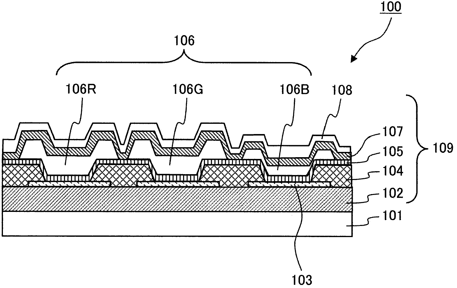
[0138] First, a method of manufacturing an organic EL panel in which an organic film is formed on an organic EL substrate patterned by the laser transfer method of the present invention will be described. figure 1 It is a sectional view of the organic EL substrate of Example 1. exist figure 1 Among them, 100 represents an organic EL substrate. 101 denotes a driving circuit substrate having a driving circuit such as a TFT (Thin Film Transistor) formed on a glass substrate, 102 denotes a planarization layer made of polyimide or the like provided on the driving circuit substrate 101, and 103 denotes an organic EL The lower electrode of the element is a first electrode made of a conductive thin film, 104 denotes an insulating bank covering the end of the first electrode, 105 to 107 denote an organic film constituting an organic EL element, and 108 denotes a second electrode serving as an upper electrode. 109 denotes the above-mentioned organic EL element forming portion provided...
Embodiment 2
[0202] Figure 10 It is a schematic diagram showing the structure of the organic EL substrate 300 of Example 2. Figure 10 In this method, after sequentially forming a planarization layer 102, a first electrode 103, a bank 104, and an organic film 105 as a common layer on a driving circuit substrate 101, an organic film as a light-emitting element with each color separated in a pattern is formed according to the present invention. 106R, 106G, 106B and pattern-separated organic films 107R, 107G, 107B, and then, the second electrode 108 as a common layer is formed.
[0203] In the organic EL substrate 300 , organic films 107R, 107G, and 107B are included in organic films 106A, 106B, and 106C that are pattern-separated light-emitting elements. Other construction and manufacturing methods and figure 1 The organic EL substrate 100 shown is the same.
Embodiment 3
[0205] Figure 11 It is a schematic diagram showing the structure of the organic EL substrate 400 of Example 3. exist Figure 11 In the present invention, after the planarization layer 102, the first electrode 103, and the bank 104 are sequentially formed on the driving circuit substrate 101, the pattern-separated organic films 105R, 105G, 105B and the organic film of the pattern-separated light-emitting element are formed according to the present invention. films 106R, 106G, 106B, and then, an organic film 107 as a common layer and a second electrode 108 as a common layer are formed.
[0206] In the organic EL substrate 400 , organic films 105R, 105G, and 105B are included in pattern-separated organic films 106R, 106G, and 106B. Other construction and manufacturing methods and figure 1 The organic EL substrate 100 shown is the same.
PUM
| Property | Measurement | Unit |
|---|---|---|
| thickness | aaaaa | aaaaa |
Abstract
Description
Claims
Application Information
 - Generate Ideas
- Intellectual Property
- Life Sciences
- Materials
- Tech Scout
- Unparalleled Data Quality
- Higher Quality Content
- 60% Fewer Hallucinations
Browse by: Latest US Patents, China's latest patents, Technical Efficacy Thesaurus, Application Domain, Technology Topic, Popular Technical Reports.
© 2025 PatSnap. All rights reserved.Legal|Privacy policy|Modern Slavery Act Transparency Statement|Sitemap|About US| Contact US: help@patsnap.com


