Video display apparatus

A technology of image display device and display panel, which is applied to static indicators, nonlinear optics, instruments, etc., can solve the problems that the device is difficult to obtain intensity, and the depth space becomes smaller.

Inactive Publication Date: 2010-03-31
HITACHI LTD
View PDF1 Cites 11 Cited by
  • Summary
  • Abstract
  • Description
  • Claims
  • Application Information

AI Technical Summary

Problems solved by technology

However, the pursuit of thinning will lead to a reduction in the sufficient depth space, making it difficult to obtain sufficient strength for the entire device

Method used


Image

  • Video display apparatus
  • Video display apparatus
  • Video display apparatus

Examples


Embodiment Construction

[0050] Hereinafter, embodiments of the image display device of the present invention will be described by taking a color liquid crystal television using a liquid crystal panel module of an edge-type LED backlight as an example with reference to the drawings.

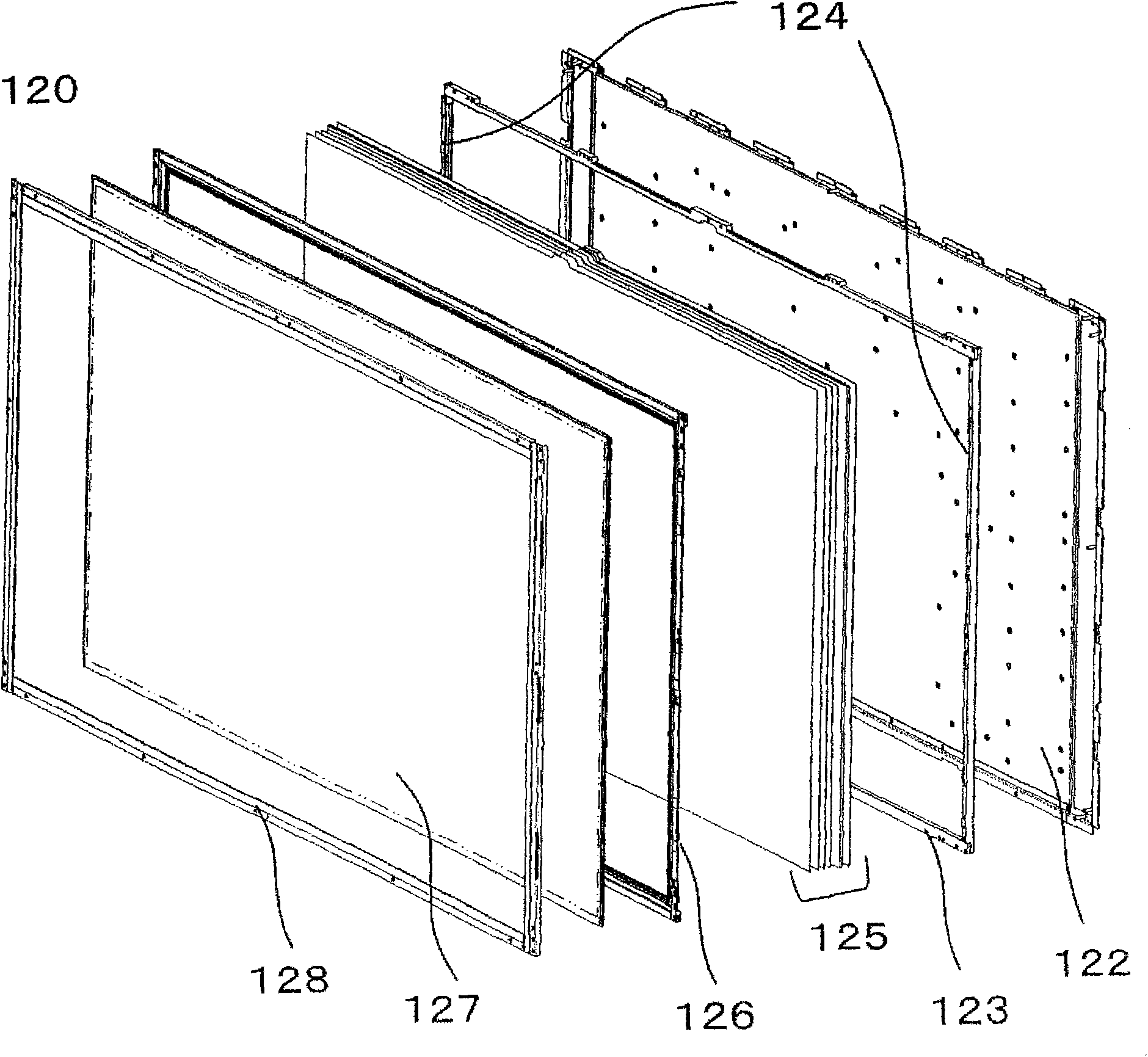
[0051] figure 1 It is a perspective view of the image display device of this embodiment. The image display device 100 includes a panel module 120 and a front frame 110 as a casing surrounding the panel module 120 . The image display device 100 stands on the base 150 , and the display screen 121 on which the panel module 120 is disposed is exposed from the front opening of the front frame 110 .

[0052] Here, for convenience of description, the up, down, left, right, front, and back are defined based on the display screen 121 of the image display device 100 . That is: when the user of the audio-visual image display device 100 is facing the display screen 121, the side of the near display screen 121 is "front", and the f...


PUM


Abstract

The present invention provides a simply usable shield cover capable of enhancing the mechanical strength of a set even if a display device is decreased in thickness. In a video display apparatus including a base chassis on a front surface of which a displaying member is arranged and on a back surface of which a unit for driving and controlling the display device is arranged, and a plurality of frames arranged on the back surface of the base chassis in parallel with each other, a shield cover is attached to the plurality of frames to extend over those to form a crosslink structure.

Description

technical field [0001] The present invention relates to an image display device using a flat panel such as a liquid crystal panel as a display panel. Background technique [0002] Display devices such as liquid crystal televisions and plasma televisions tend to become thinner every year. However, the pursuit of thinning will lead to a reduction in the sufficient depth space, making it difficult to obtain sufficient strength for the entire device. To solve this problem, for example, Patent Document 1 discloses a prior art that can secure strength while keeping the depth of the image display device thin. [0003] Patent Document 1 discloses the following content. A main frame as a reinforcing part is arranged on the back side of the panel module, and the reinforcing frame is assembled on this main frame to increase the strength of the main frame. Strength of. [0004] 【Patent Document 1】JP-A-2006-39062 Contents of the invention [0005] In recent years, image display dev...

Claims


Application Information

Patent Timeline
Patent Type & Authority Applications(China)
IPC IPC(8): G02F1/13G02F1/133
CPCG02F1/133308G02F2001/133314G02F2201/54G02F1/133314
Inventor 山本拓佐藤克成山下芳春三井津健小椋弘善细野宏树佐藤公一
Owner HITACHI LTD
Why Eureka
Try Eureka