
Double-control bent electrophysiological catheter

An electrophysiology and catheter technology, applied in catheters, medical science, heating surgical instruments, etc., can solve the problems of inconvenient control and operation, inconvenient use, and easy finger fatigue, and achieve the effects of convenient assembly, smooth movement and smooth operation.

Active Publication Date: 2014-02-12
四川锦江电子医疗器械科技股份有限公司
View PDF8 Cites 13 Cited by
  • Summary
  • Abstract
  • Description
  • Claims
  • Application Information

AI Technical Summary

Problems solved by technology

Due to the complex physiological structure of the human body, a handle with superior manipulability is required to control the catheter, and it is extremely challenging to control the catheter to accurately reach different lesions
[0003] In order to solve this problem, people have adopted catheters and their control handles of various structures, such as a dual-control catheter and control handle disclosed in US Patent Application US2008039918A1, the distal end of the catheter can be bent or adjusted. Diameter, in which bending and adjusting the diameter of the helical part are achieved by manipulating the two control keys on the handle respectively. During the actual operation, the user needs to adjust separately, which is inconvenient to directly realize the control and operation of the catheter with one hand
[0004] The control keys for controlling the guide wires on the existing catheter control handle with dual guide wires inside are usually set separately. During use, the fingers need to be continuously moved in a large range to control different operation keys, which makes it inconvenient to use and easy to use with fingers. fatigue

Method used


Image

  • Double-control bent electrophysiological catheter
  • Double-control bent electrophysiological catheter
  • Double-control bent electrophysiological catheter

Examples


Embodiment Construction

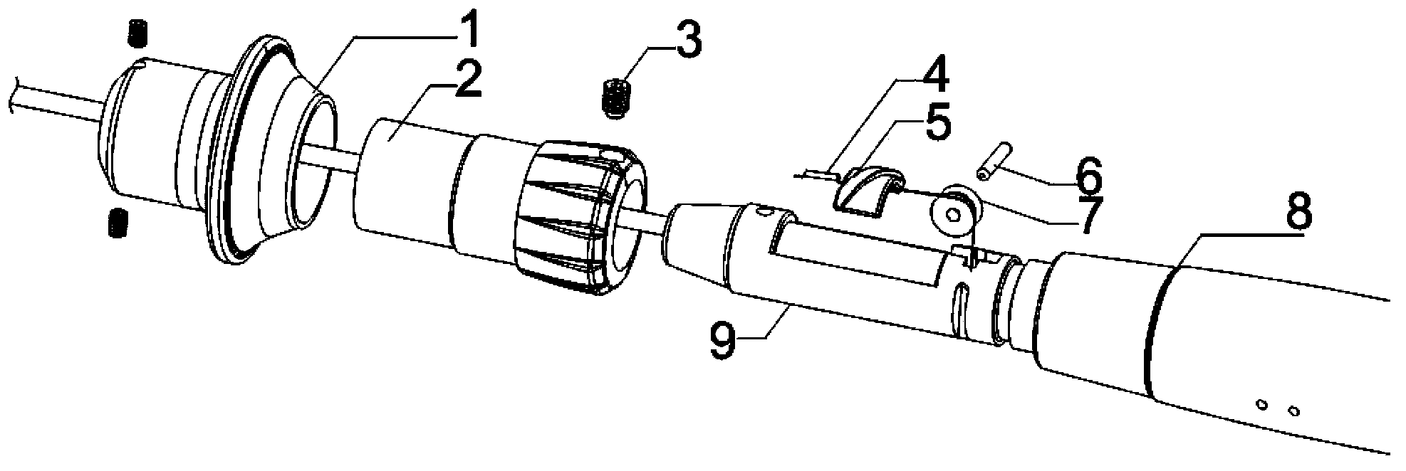
[0020] A specific embodiment of the present invention, a handle of a dual-control bending electrophysiological catheter, such as figure 1 As shown, it includes the handle body 8, the mandrel 9 is installed in the handle body 8, and can slide along the handle body 8, the control key 1 is fixed on the mandrel 9, and constitutes the push-pull control key together with the mandrel 9, and the catheter and the push-pull control key Fixed together, the first guide wire passes through the mandrel 9 and is fixed inside the handle body 8. When the push-pull control key is pushed, the relative position of the catheter and the first guide wire changes, and the distal end of the catheter will bend; on the mandrel 9 there is A section of annular groove, the rotary control key 2 is installed on the mandrel 9, the screw 3 passes through the rotary control key 2, the head of the screw 3 is located in the annular groove, and is used to define the axis of the rotary control key 2 and the push-pul...


PUM


Abstract

A double-control bent electrophysiological catheter comprises a catheter body, a first guiding wire, a second guiding wire, a handle body, a push-and-pull control key and a rotary control key, wherein the first guiding wire and the second guiding wire are arranged in the catheter body; the handle body is connected with the catheter body; the push-and-pull control key and the rotary control key are arranged on the handle body and respectively control the first guiding wire and the second guiding wire; and two or more than two bent sections are arranged at a distal end of the catheter body. The double-control bent electrophysiological catheter is characterized in that the push-and-pull control key and the rotary control key are arranged on the handle body in a matched manner and synchronously slide along the length direction; and the rotary control key can rotate relative to the push-and-pull control key. The push-and-pull control key and the rotary control key of the double-control bent electrophysiological catheter synchronously slide, and can be controlled by a user with a single hand. Because the push-and-pull control key and the rotary control key can be directly pushed by the user with the single hand, the double-control bent electrophysiological catheter is convenient to control and use.

Description

technical field [0001] The invention relates to a medical catheter, in particular to a conveniently operated double-control bending electrophysiological catheter. Background technique [0002] Catheter tubing is usually made of flexible, biocompatible materials, such as plastics, including polyethylene, polyester, or polyamide. Due to the complex physiological structure of the human body, a handle with superior manipulability is required to control the catheter, and it is extremely challenging to control the catheter to accurately reach different lesions. [0003] In order to solve this problem, people have adopted catheters and their control handles of various structures, such as a dual-control catheter and control handle disclosed in US Patent Application US2008039918A1, the distal end of the catheter can be bent or adjusted. Diameter, in which bending and adjusting the diameter of the helical part are achieved by manipulating the two control keys on the handle respective...

Claims


Application Information

Patent Timeline
IPC IPC(8): A61B18/14
CPCA61B18/1492A61B2017/00323A61B2018/00196A61B2018/00202A61B2018/00214A61B2018/00946A61B2018/00952A61M25/0136
Inventor 李楚武王建聪刘春宝
Owner 四川锦江电子医疗器械科技股份有限公司
Learn More