Vacuum-operated booster

Inactive Publication Date: 2006-06-01
ADVICS CO LTD
View PDF4 Cites 9 Cited by
  • Summary
  • Abstract
  • Description
  • Claims
  • Application Information

AI Technical Summary

Benefits of technology

[0012] In the vacuum-operated booster of the present invention, when the booster is in the low-load servo region in which the output of the output shaft is equal to or less than the set value, the reaction force dividing mechanism can transmit all reaction force of output of the output shaft only to the plunger. Therefore, in the low-load servo region in which the output of the output shaft is equal to or less than the set value, the servo ratio (output / input) becomes approximately 1. Accordingly, in a vehicle which is equipped with the above vacuum-operated booster and employs a brake system which increases electric power regeneration efficiency, the electric power regeneration efficiency can be increased to a sufficient level.
[0022] When the present invention is practiced, the reaction member may be axially movable in contact with the inner wall of the axial hole of the valve body via a single annular projection formed on the outer periphery of the reaction member. Therefore, axial movement of the reaction member in relation to the inner wall of the axial hole of the valve body (operation in the low-load servo region) becomes smooth, whereby operation of the vacuum-operated booster in the low-load servo region can be made smooth.

Problems solved by technology

However, during a high-input operation, which takes places after the sleeve comes into engagement with the stepped portion of the valve body, the reaction force transmitted from the reaction member via the reaction force transmission / cutoff mechanism is transmitted to the stepped portion of the valve body, so that the plunger becomes unable to receive the reaction force from the reaction member via the reaction force transmission / cutoff mechanism despite the plunger receiving the reaction force directly from the reaction member.
Therefore, in the case where a vehicle is equipped with the above-described vacuum-operated booster and employs a brake system which increases electric power regeneration efficiency, increasing the electric power regeneration efficiency to a sufficient level is difficult.
Moreover, in the vacuum-operated booster disclosed in the above-mentioned publication, when the sleeve of the reaction force transmission / cutoff mechanism moves rearward against the load of the compression spring, an intermediate portion of the compression spring may be caught by (come into engagement with) the spring seat fixed to the plunger or the plunger itself, which may result in generation of noise and hinder smooth operation.
Further, since the spring seat, the compression spring, and the sleeve of the reaction force transmission / cutoff mechanism must be individually assembled to the plunger, ease of assembly is poor.

Method used


Image

  • Vacuum-operated booster
  • Vacuum-operated booster
  • Vacuum-operated booster

Examples


Embodiment Construction

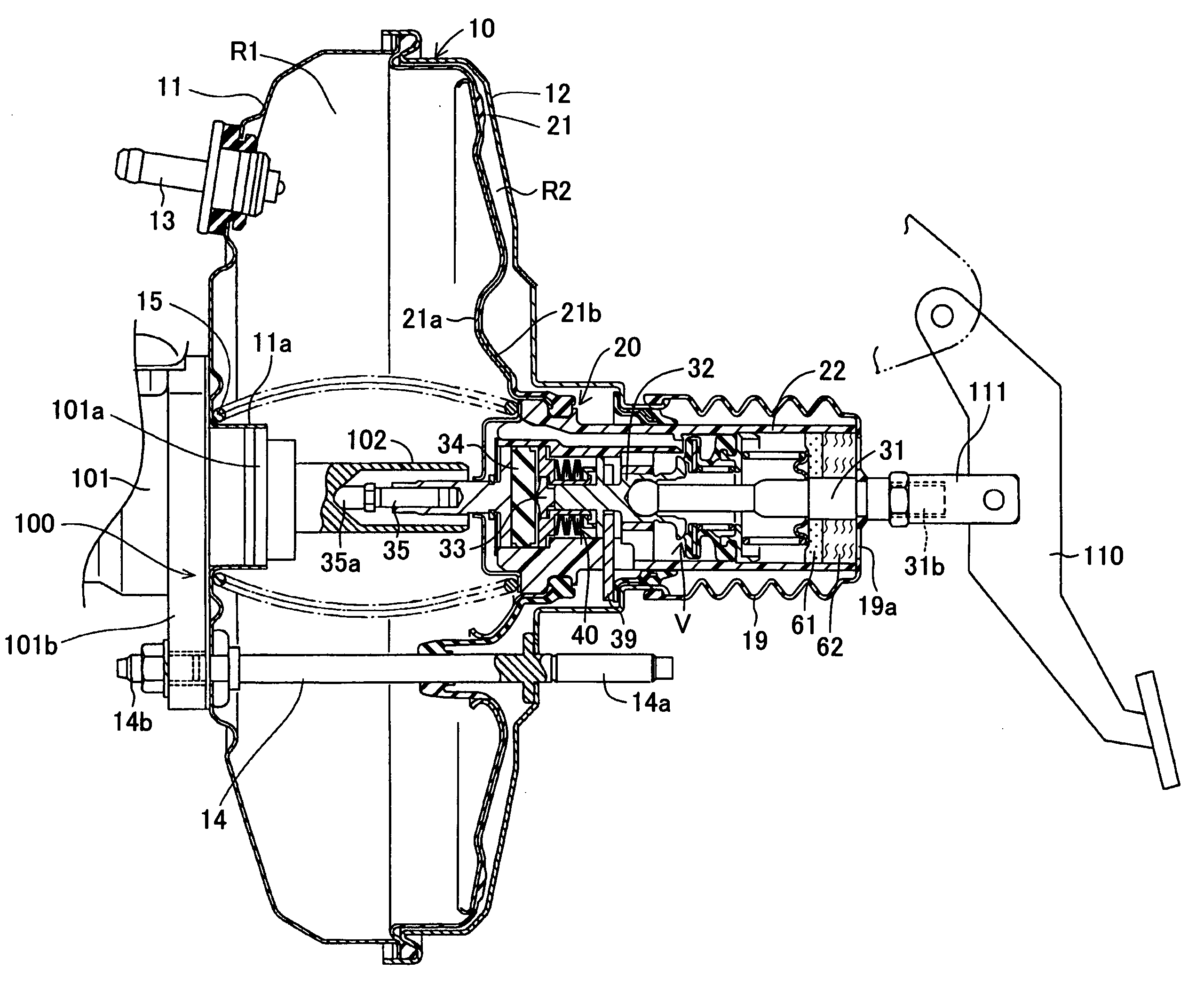
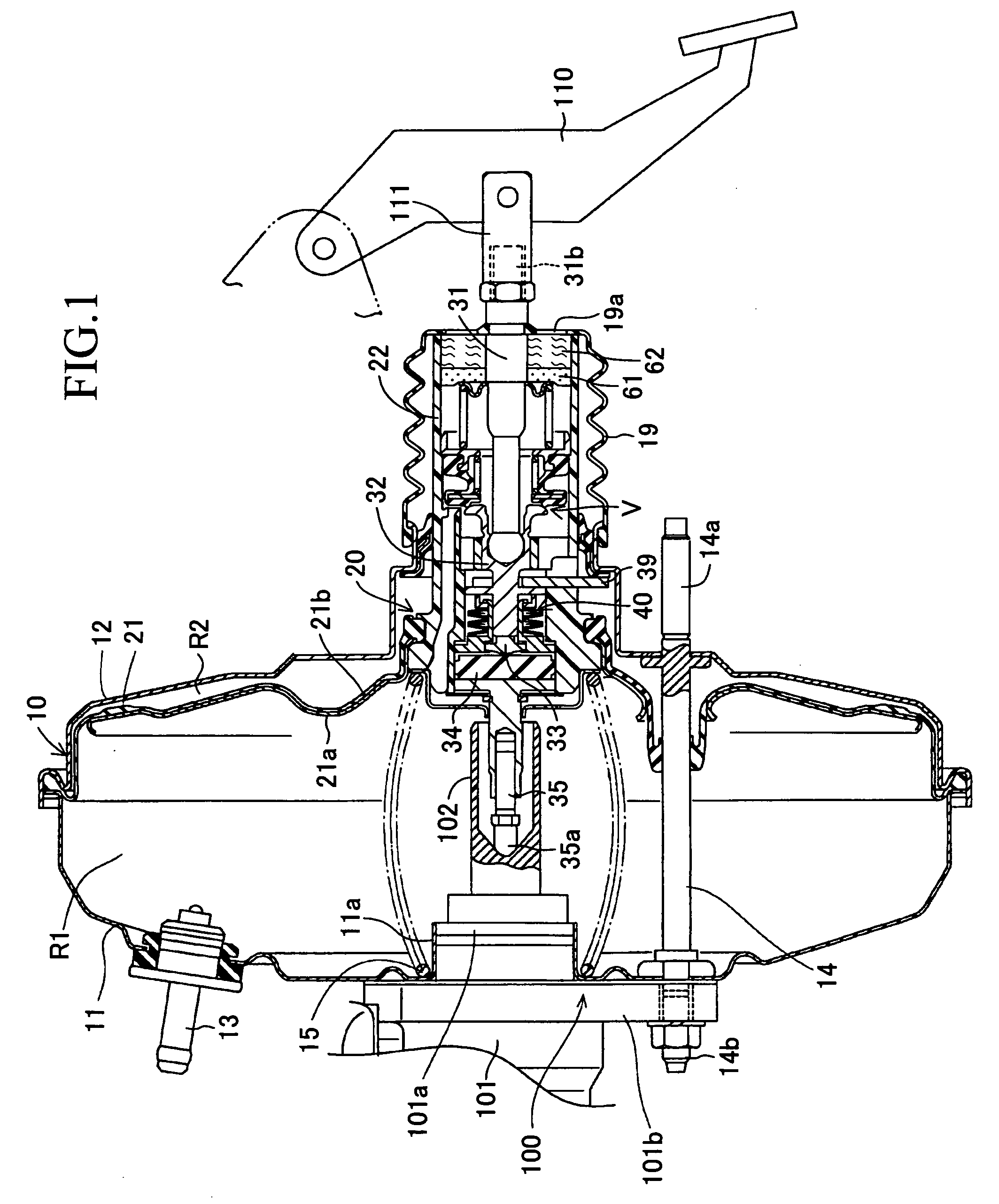
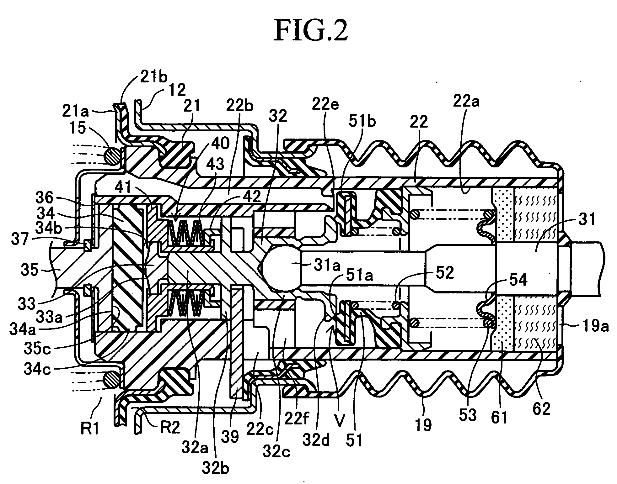
[0029] An embodiment of the present invention will next be described in detail with reference to the drawings. FIGS. 1 to 3 show an embodiment in which the present invention is applied to a vacuum-operated booster of a brake system for a vehicle. In the vacuum-operated booster of the present embodiment, a power piston 20 including a movable diaphragm 21 and a valve body 22 is assembled to a housing 10, and the interior of the housing 10 is divided into a constant-pressure chamber R1 and a variable-pressure chamber R2 by means of the movable diaphragm 21.

[0030] As shown in FIG. 1, the housing 10 includes a front shell 11 and a rear shell 12, and is provided with a vacuum (negative-pressure) introduction pipe 13 for establishing communication between the constant-pressure chamber R1 and a vacuum source (e.g., the intake manifold of an unillustrated engine) at all times. The housing 10 is fixedly attached to a stationary member; i.e., a vehicular body (not shown), by means of threaded...


PUM


Abstract

Reaction force from a reaction member is divided and transmitted to a front shaft portion of a plunger via abutment member and to a flange portion of the plunger via a spring unit. The spring unit includes a tubular first holding member assembled to the front shaft portion of the plunger and being engageable, at its front end portion, with the reaction member, a second holding ember assembled to a rear end portion of the first holding member and having a rear end portion which extends rearward from the first holding member for engagement with the flange portion, and Belleville springs held between the first and second holding members. When the reaction force transmitted from the reaction member to the first holding member exceeds the load of the springs, the first holding member moves while compressing the springs and engages with a stepped portion of a valve body.

Description

BACKGROUND OF THE INVENTION [0001] 1. Field of the Invention [0002] The present invention relates to a vacuum-operated booster which has a movable diaphragm dividing the interior of a housing into a constant-pressure chamber and a variable-pressure chamber and which boosts an input by means of atmospheric pressure difference between the constant-pressure chamber and the variable-pressure chamber and outputs the boosted force. [0003] 2. Description of the Related Art [0004] A vacuum-operated booster of the above-described type is disclosed in, for example, Japanese Patent Application Laid-Open (kokai) No. H10-230840. In the disclosed vacuum-operated booster, a valve body, which is connected to the movable diaphragm dividing the interior of the housing into a constant-pressure chamber and a variable-pressure chamber, has an axial hole, and a valve mechanism is built in the axial hole. The valve mechanism includes, as constituent elements, an input shaft, which is axially movable with ...

Claims


Application Information

Patent Timeline
IPC IPC(8): F15B9/10
CPCB60T13/575
Inventor TSUBOUCHI, KAORU
Owner ADVICS CO LTD
Why Eureka
Try Eureka