
Wireless self-inspection mouth mirror

An oral mirror and wireless technology, applied in the field of oral observation devices, can solve the problems of easy infection of bacteria, inconvenient operation, and the shape of the camera rod 1 does not conform to daily usage habits, so as to avoid cross-use infection of bacteria, convenient use, and convenient operation Effect

Inactive Publication Date: 2014-02-12
钱大宏
View PDF12 Cites 11 Cited by
  • Summary
  • Abstract
  • Description
  • Claims
  • Application Information

AI Technical Summary

Problems solved by technology

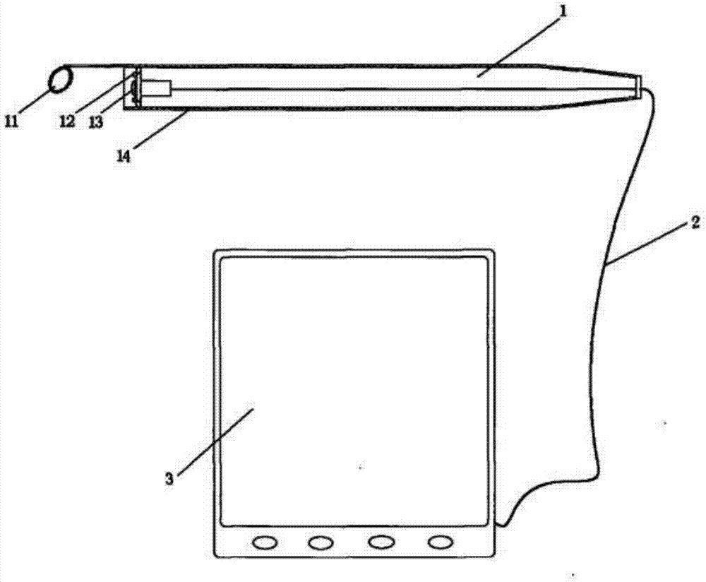
[0006] 1. The shape of the camera rod 1 does not conform to people's daily use habits;
[0007] 2. The camera pole 1 needs to be used in conjunction with the handheld image display 3 through the connection line 2, and the operation is not convenient enough;
[0008] 3. A dedicated handheld image display is required, and it needs to be powered by a battery, which is not convenient and environmentally friendly;
[0009] 4. Dental mirrors, as non-disposable observation equipment, have no effective disinfection and cleaning methods, and are prone to bacterial infection

Method used


Image

  • Wireless self-inspection mouth mirror
  • Wireless self-inspection mouth mirror
  • Wireless self-inspection mouth mirror

Examples


Embodiment 1

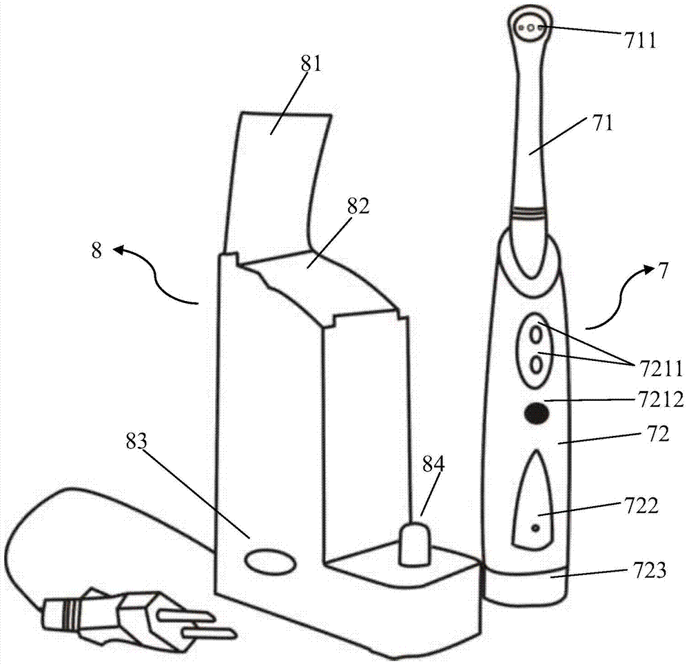
[0037] Such as image 3 As shown, the wireless self-examination dental mirror 7 of the present invention has an overall shape similar to that of a toothbrush, including an observation part 71 and a hand-held part 72. The observation part 71 is a sealed structure with a transparent end and a built-in camera assembly. Such as Figure 4 As shown, the shooting assembly includes at least one camera 7111 (the camera is preferably a high-definition camera) and at least one LED 7112 for lighting (the two LEDs are shown on the sides or around the camera as shown in the figure), and the handle 72 There is a wireless transmission module (not shown in the figure) for transmitting image data inside. In the self-inspection oral mirror 7 of the present invention, the handle 72 has a switch 7212, a button 7211 and an indicator light 722 (different states of the indicator light, such as different colors or flashing indicate different operation modes). The keys include a video recording key, ...

Embodiment 2

[0042] Such as Figure 6 As shown, the difference from Embodiment 1 is that the charging base 8 has an ozone generating module and an ozone disinfection chamber (not shown in the figure) for cleaning and disinfection, and the storage box cover 81 is opened, and the wireless self-checking oral mirror The observation part 71 of 7 is placed in the ozone disinfection chamber, and the ozone generation sheet is arranged in the ozone disinfection chamber, and the whole disinfection and cleaning of the observation part 71 is carried out automatically by pressing the opening button 85 of the ozone disinfection chamber.

[0043] Preferably, the charging base has a wireless receiving module (built-in, not shown in the figure) and a display 86 . The display 86 can be arranged on the side of the base (this design can save a separate or dedicated handheld image display), which is convenient for users to observe.

[0044] As can be seen from the above technical solutions, the present invent...


PUM


Abstract

The invention discloses a wireless self-inspection mouth mirror. The whole of the wireless self-inspection mouth mirror is shaped like a toothbrush, the wireless self-inspection mouth mirror comprises an observation part and a handheld part, wherein the observation part is of a leakproof structure; the end parts of the observation part are transparent; a shooting assembly is built in the observation part; the shooting assembly comprises at least one camera and one or more than one LED (Light Emitting Diode) for illumination; a wireless transmission module which is used for transmitting image data is arranged inside the handheld part. By using the wireless self-inspection mouth mirror, a user can conveniently observe the parts inside the oral cavity, processing modes of cleaning and sterilizing are realized, and the bacteria cross infection of the oral cavity is avoided.

Description

technical field [0001] The invention relates to an oral cavity observation device, in particular to a wireless self-inspection oral cavity mirror. Background technique [0002] With the improvement of people's living and cultural level, people have gradually improved their awareness of their own health, and the medical and health services have also been significantly improved. This is not only reflected in the development and research of medical drugs, but also in the reform and development of medical equipment. Innovation aspect. At present, many medical units at home and abroad basically have stomatology departments. Doctors can judge the patient's oral diseases based on the observation of the patient's oral cavity, including some diseases that are not the oral cavity itself. The condition of the medical record and symptoms of the patient provides a more sufficient basis for the doctor to judge the patient's disease, so the oral examination has become particularly importa...

Claims


Application Information

Patent Timeline
Patent Type & Authority Applications(China)
IPC IPC(8): A61B1/247G08C17/02A61L2/20A61L101/10
Inventor 钱大宏
Owner 钱大宏
Learn More