
Fluorescence Observation Device and Fluorescence Observation System

An observation device, fluorescence technology, applied in medical science, image enhancement, image analysis, etc., can solve the problem of not noticing the existence of fluorescent areas, etc.

Inactive Publication Date: 2016-07-06
OLYMPUS CORP
View PDF10 Cites 0 Cited by
  • Summary
  • Abstract
  • Description
  • Claims
  • Application Information

AI Technical Summary

Problems solved by technology

Therefore, even if the fluorescent region is extracted and displayed in the image, the user may not notice the existence of the fluorescent region

Method used


Image

  • Fluorescence Observation Device and Fluorescence Observation System
  • Fluorescence Observation Device and Fluorescence Observation System
  • Fluorescence Observation Device and Fluorescence Observation System

Examples


Embodiment Construction

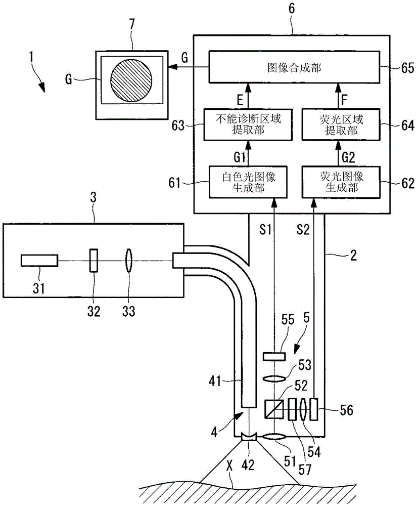
[0043] Below, refer to Figure 1 to Figure 10 A fluorescence observation device 1 according to one embodiment of the present invention will be described.

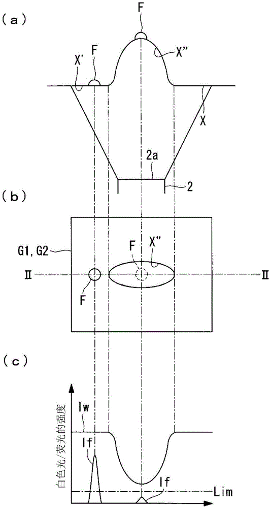
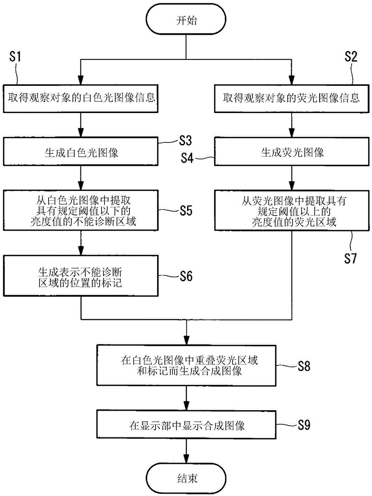
[0044] The fluorescence observation device 1 of the present embodiment is an endoscope device, such as figure 1 As shown, there is an elongated insertion part 2 inserted into the body, a light source 3, and an illumination unit 4 that irradiates excitation light and white light from the light source 3 toward the observation object X from the front end 2a of the insertion part 2, and is provided on the insertion part 2. The imaging unit 5 that acquires the image information S1 and S2 of the living tissue as the observation object X is placed on the front end 2a of the insertion part 2, and the image that processes the image information S1 and S2 acquired by the imaging unit 5 The processing unit 6 and the display unit 7 display the image G processed by the image processing unit 6 .

[0045] The light source 3 has a xenon l...


PUM


Abstract

The present invention provides a fluorescence observation device and a fluorescence observation system. The fluorescence observation device (1) has: a light source (3) for irradiating reference light and excitation light to an observation object (X); Fluorescence from the observation object (X) generated by excitation light to generate a fluorescence image (G2); a reference image generation unit (61) that captures return light from the observation object (X) generated by irradiation of the reference light and generates a reference image (G1); an image synthesis unit (65), which generates a synthesized image (G) by superimposing the fluorescence image (G2) on the reference image (G1); a discrimination unit (63), which discriminates whether there is a position with a luminance value equal to or less than a predetermined threshold; and a notification unit (65) for notifying the existence of the position when it is determined by the determination unit (63) that there is a position with a luminance value equal to or less than a predetermined threshold.

Description

technical field [0001] The invention relates to a fluorescence observation device and a fluorescence observation system. Background technique [0002] Conventionally, there is known a fluorescence observation device that extracts a fluorescence region with a higher signal level than the surrounding area as a lesion from a fluorescence image obtained by imaging an in vivo tissue, and notifies the user of the presence of the lesion (for example, refer to Patent Document 1). [0003] [Patent Document 1] Japanese Unexamined Patent Publication No. 2006-191989 [0004] In Patent Document 1, for example, a signal level 20% higher than the background level of the fluorescence image is set as a threshold, and the fluorescence region is extracted by comparing the threshold with the signal level of each pixel. However, since the fluorescence emitted from the tissue is weak, it is difficult to accurately extract the fluorescent area when the observation conditions fluctuate. Moreover,...

Claims


Application Information

Patent Timeline
Patent Type & Authority Patents(China)
IPC IPC(8): A61B1/07A61B1/05
CPCA61B1/043A61B1/00009A61B1/0005A61B1/00055G06T5/50G06T7/0014G06T2207/10121G06T2207/30088A61B5/0033
Inventor 志田裕美石原康成竹腰聪久保圭
Owner OLYMPUS CORP
Learn More