
Image-processing device and method

一种图像处理设备、图像的技术,应用在图像数据处理、图像通信、图像编码等方向,能够解决相兼容、不能低比特率等问题,达到移除块失真的效果

Active Publication Date: 2014-02-05
SONY GRP CORP
View PDF10 Cites 4 Cited by
  • Summary
  • Abstract
  • Description
  • Claims
  • Application Information

AI Technical Summary

Problems solved by technology

[0004] MPEG2 was primarily designed to encode high-quality images suitable for broadcasting, but is not compatible with lower bit rates than MPEG1 or encoding methods involving higher compression rates

Method used


Image

  • Image-processing device and method
  • Image-processing device and method
  • Image-processing device and method

Examples


no. 1 example

[0067] 1. First embodiment (image coding device)

[0068] 2. Second embodiment (image decoding device)

no. 3 example

[0069] 3. The third embodiment (example processing compatible with IPCM mode)

[0070] 4. Fourth embodiment (example processing compatible with quantization matrix)

[0071] 5. Fifth embodiment (example processing compatible with skip mode)

[0072] 6. The sixth embodiment (computer)

[0073] 7. The seventh embodiment (application example)

[0074]

[0075] [Example structure of image coding device]

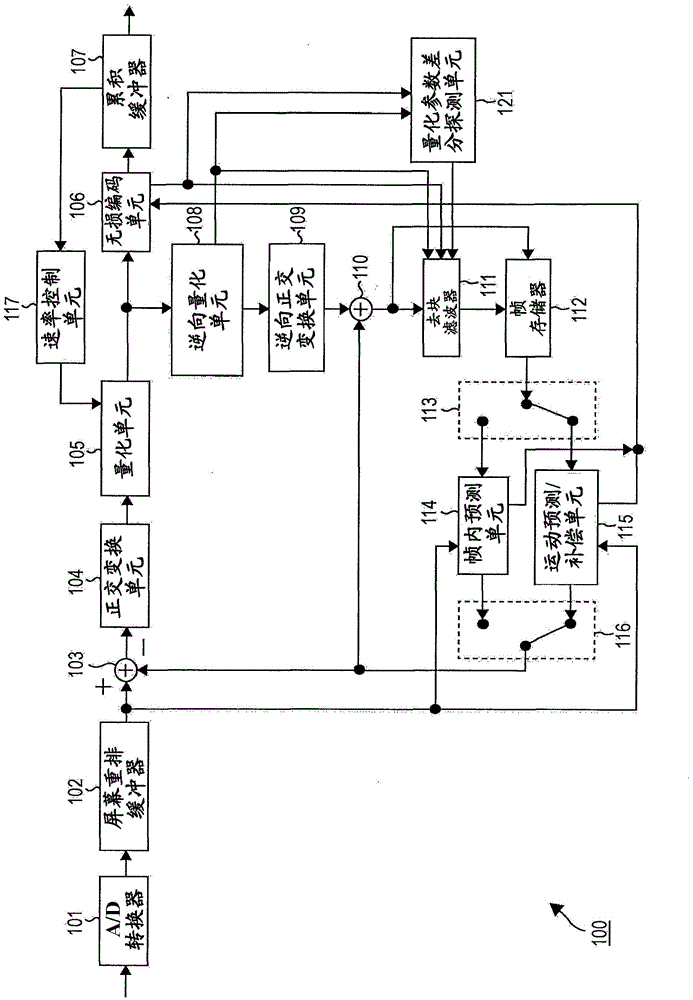
[0076] figure 1 The structure of one embodiment of an image encoding device as an image processing device to which the present invention is applied is shown.

[0077] figure 1 The image encoding device 100 shown encodes image data through prediction processing. The encoding method used here may be, for example, H.264 and MPEG (Moving Picture Experts Group) 4 Part 10 (AVC (Advanced Video Coding)) (hereinafter referred to as H.264 / AVC), or HEVC (High Efficiency Video Coding).

[0078] in figure 1 In the illustrated embodiment, the image encoding device 100 includes an A / D (analog / digital) c...

no. 2 example

[0266] [Image coding equipment]

[0267] Figure 13 The structure of one embodiment of an image encoding device as an image processing device to which the present invention is applied is shown. Figure 13 The image decoding device 200 shown is compatible with figure 1 The image encoding device 100 shown is a compatible decoding device.

[0268] The data encoded by the image encoding device 100 is transmitted to the image decoding device 200 compatible with the image encoding device 100 through a predetermined transmission path, and then decoded.

[0269] Such as Figure 13 As shown, the image decoding device 200 includes an accumulation buffer 201, a lossless decoding unit 202, an inverse vectorization unit 203, an inverse orthogonal transform unit 204, an arithmetic operation unit 205, a deblocking filter 206, a screen rearrangement buffer 207, and D / A converter 208. The image decoding device 200 further includes a frame memory 209, a selection unit 210, an intra prediction unit ...


PUM


Abstract

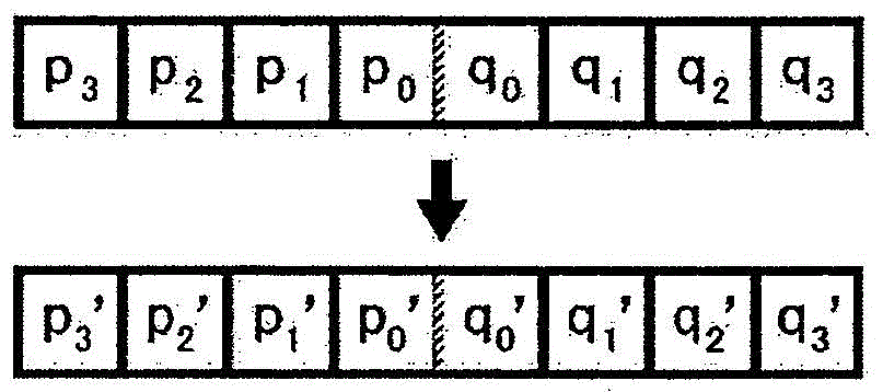
The present technique relates to image processing devices and methods for enabling more appropriate removals of block distortions. When the difference between the quantization parameter QPc of a current region C and the quantization parameter QPN of a neighboring region N is determined to be larger than a predetermined threshold value, a deblocking filter adjusts the deblocking filtering operation so that stronger filtering is performed on a boundary between the current region and the neighboring region. This disclosure can be applied to image processing devices, for example.

Description

Technical field [0001] The present invention relates to an image processing device and method, and more particularly, to an image processing device and a method more suitable for removing block distortion. Background technique [0002] In recent years, devices that compress images by executing an encoding method for compressing image information have been widely used, thereby manipulating image information as digital information, and by doing so, realizing efficient information transmission and accumulation, in which compressed images pass through orthogonal Transformation (such as discontinuous cosine transform) and motion compensation by using the inherent redundancy of image information are achieved. This coding method may be, for example, MPEG (Moving Picture Experts Group). [0003] In particular, MPEG2 (ISO / IEC13818-2) is defined as a general purpose image coding standard, and can be used for interlaced images and non-interlaced images, as well as standard resolution images ...

Claims


Application Information

Patent Timeline
Patent Type & Authority Applications(China)
IPC IPC(8): H04N19/117H04N19/176H04N19/86
CPCH04N19/00212H04N19/0026H04N19/00066G06T9/00H04N19/0009H04N19/00909H04N19/117H04N19/124H04N19/157H04N19/17H04N19/86
Inventor 佐藤数史
Owner SONY GRP CORP
Learn More