
Long wave infrared three-view-field optical system

An optical system, long-wave infrared technology, applied in the field of optical imaging, can solve the problems of increased weight, increased volume of the whole machine, long travel of optical components, etc., and achieves the effect of simple assembly, compact structure, and mass production.

Active Publication Date: 2014-02-05
KUNMING INST OF PHYSICS
View PDF5 Cites 11 Cited by
  • Summary
  • Abstract
  • Description
  • Claims
  • Application Information

AI Technical Summary

Problems solved by technology

Through the implementation of the present invention, only one optical flat plate needs to be inserted, which can effectively reduce the number of optical components and mechanisms to be inserted, and the problem of optical axis consistency in the process of assembly and adjustment is well solved; changing the intermittent intermittent zoom system can To realize the change of three focal lengths, but need to move more than two sets of optical components, and the travel of the optical components will be longer, which will increase the volume of the whole machine and lead to an increase in weight

Method used


Image

  • Long wave infrared three-view-field optical system
  • Long wave infrared three-view-field optical system
  • Long wave infrared three-view-field optical system

Examples


Embodiment Construction

[0024] The present invention will be further described in detail through the embodiments below in conjunction with the accompanying drawings.

[0025] This embodiment is an example in which the present invention is applied to a cooling type 384×288 element 25 μm staring type focal plane detector.

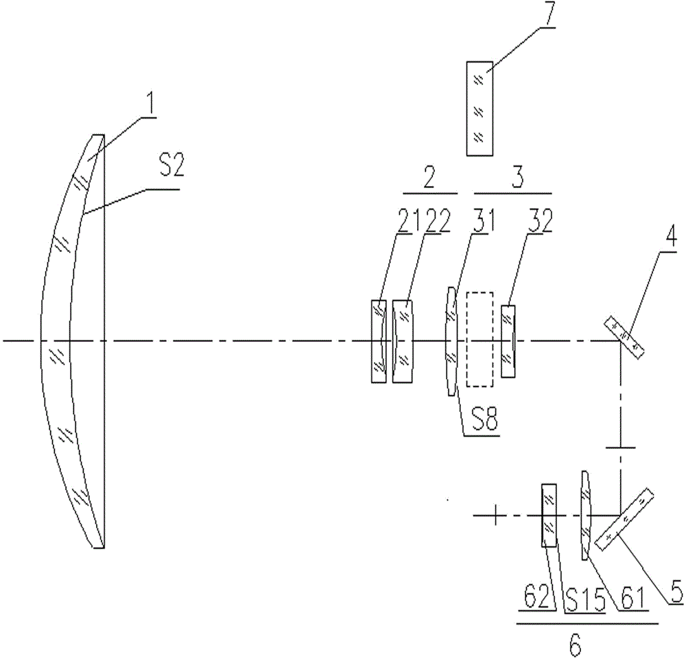
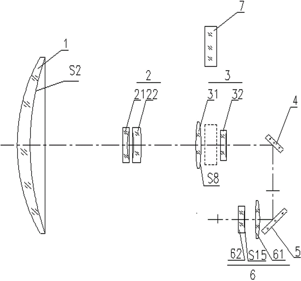
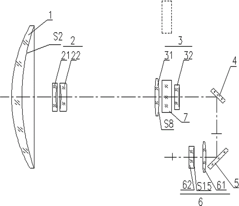
[0026] figure 1 , figure 2 , image 3 They are respectively schematic diagrams of the long-wave infrared three-field optical system in the present invention at the telephoto, medium-focus and short-focus positions. It is characterized in that: from the object side to the image side, there are front fixed group 1 with positive refractive power, zoom group 2 with negative refractive power, rear fixed group 3 with positive refractive power, optical flat plate 7, first reflector 4, The second reflection mirror 5 is composed of a secondary imaging group 6 with positive refractive power.

[0027] Wherein, the front fixed group 1 is a meniscus germanium positive lens with a convex sur...


PUM

PropertyMeasurementUnit
Thicknessaaaaaaaaaa

Abstract

The invention provides a long wave infrared three-view-field optical system. The optical system is sequentially composed of a front fixing set, a zoom set, a rear fixing set, an optical flat, a first reflecting mirror, a second reflecting mirror and a secondary image forming set from object space to image space. High order aspheric surfaces are adopted in a second surface of a lens of the front fixing set, a second surface of a first lens in the rear fixing set and a first surface of a second lens in the secondary image forming set. The working wave band of the optical system ranges from 7.7 micrometers to 9.5 micrometers, F # is 3, view fields are respectively 0.96 degree * 0.72 degree, 6 degrees * 4.5 degrees and 27 degrees * 21 degrees. The zoom set is moved, the optical flat is inserted, then, the large view field, the middle view field and the small view field can be achieved, consistency of optical axes of the three view fields is good; the zoom ratio can reach 28 times to the maximum, and image forming quality is good; the maximum stroke of the zoom set is smaller than 100mm, and 100% cold shield efficiency is achieved; an optical path is designed to be folded in a U type, and then the optical system is small in size, compact in structure and easy to adjust, and can be massively produced.

Description

technical field [0001] The invention belongs to the technical field of optical imaging, and relates to a long-wave infrared three-field optical system. Background technique [0002] High-resolution infrared imaging systems have a wide range of requirements in navigation, observation, tracking, and aiming. The temperature of the ground target is low, and the radiation energy is small, and its infrared radiation is mostly concentrated in the infrared long-wave band. The infrared optical system is an important part of the infrared imaging system, which is used for converging infrared radiation energy, zooming, cooling, controlling imaging quality and focusing infrared radiation energy on the focal plane. Due to the single function of the single-field infrared optical system, the actual use is limited, and it is difficult to meet the development needs of modern infrared optical systems. Since the three-field infrared optical system has three fields of view with different sizes...

Claims


Application Information

Patent Timeline
IPC IPC(8): G02B15/00G02B7/182
Inventor 冯晓燕陈吕吉李萍
Owner KUNMING INST OF PHYSICS
Learn More