A light and small dual-axis photonic crystal fiber optic gyroscope skeleton

A photonic crystal fiber, light and small technology, applied in the direction of Sagnac effect gyroscope, gyroscope/steering sensor equipment, measuring device, etc., can solve the problem that the performance of ordinary optical fiber is greatly affected, the increase of fiber loss, and the increase of fiber loss and other issues, to achieve the effect of reducing material consumption and volume, facilitating installation and debugging, and improving accuracy

Active Publication Date: 2016-02-17
BEIHANG UNIV
View PDF4 Cites 0 Cited by
  • Summary
  • Abstract
  • Description
  • Claims
  • Application Information

AI Technical Summary

Problems solved by technology

In the light and small design process of the gyroscope, these factors have a great influence on the performance of ordinary optical fibers, such as the increase in fiber loss as the size of the fiber ring decreases, poor temperature stability, large birefringence and extinction ratio, and in the case of nuclear radiation, the fiber core The doping in the fiber is easy to diffuse and cause additional increase in fiber loss, etc.

Method used


Image

  • A light and small dual-axis photonic crystal fiber optic gyroscope skeleton
  • A light and small dual-axis photonic crystal fiber optic gyroscope skeleton
  • A light and small dual-axis photonic crystal fiber optic gyroscope skeleton

Examples


Embodiment Construction

[0080] The present invention will be further described in detail below with reference to the drawings and embodiments.

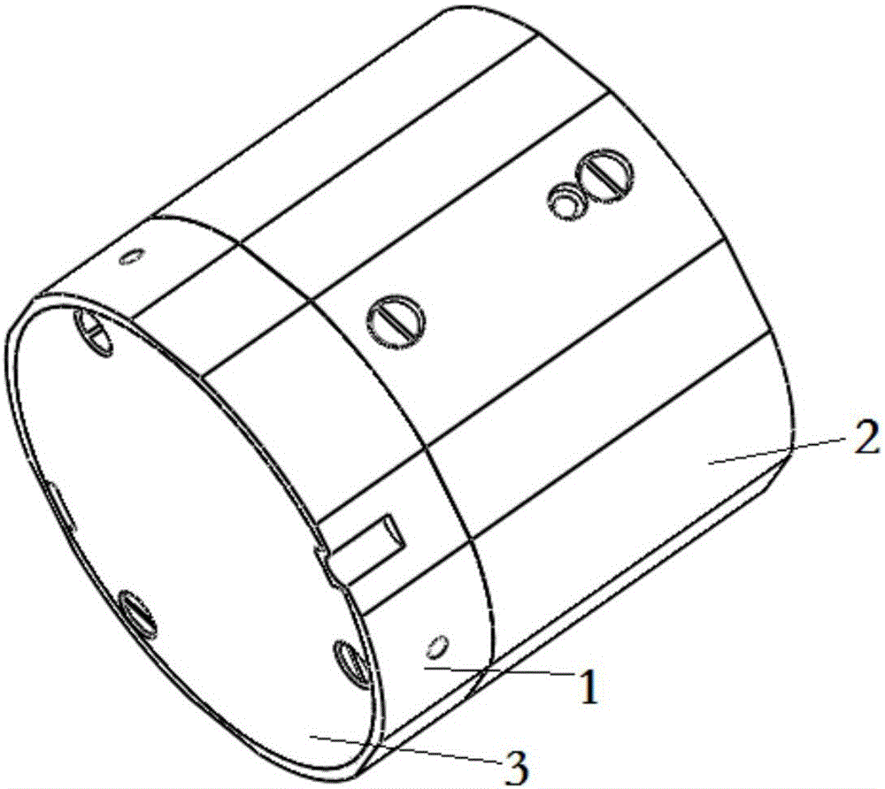
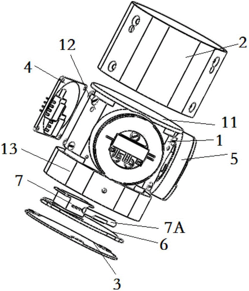
[0081] The present invention is a light and small biaxial photonic crystal fiber gyroscope skeleton, such as figure 1 , Figure 1A As shown, it includes a skeleton body 1, an outer cover 2, a lower cover 3, a front release board 4, a ring assembly 5, a light source board 6 and a light source 7.

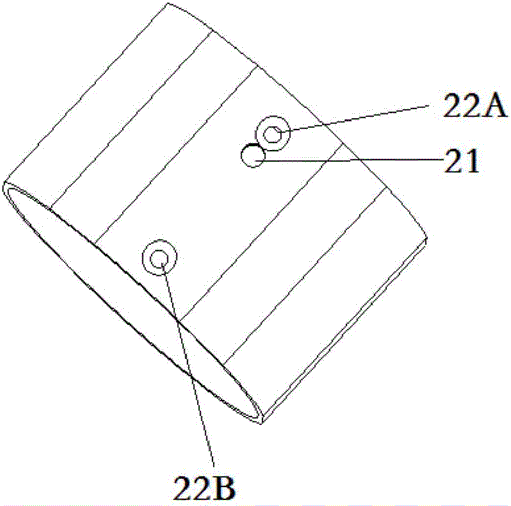
[0082] The outer cover 2 is connected with the threaded holes 12A21 and 12A22 in the middle of the frame body 1 by countersunk screws to achieve a fixed connection; the front plate 4 is installed on the front plate surface 123 in the middle of the frame body 1, and the two fiber ring components are respectively installed on the frame body 1 the ring assembly surfaces 121 and 122 in the middle; the light source plate 6 is installed in the bottom of the skeleton body 1; the lower cover 3 is installed at the lower end of the skeleton body 1.

[0083] Skeleton body 1 such as ...


PUM


Abstract

The invention discloses a light small biaxial photonic crystal optical fiber gyroscope framework which comprises a framework body, an outer cover, a front plate and a lower cover, wherein the framework body comprises three cross sections of the side surface of a cylinder and a bottom surface of the cylinder; two optical fiber ring assemblies are mounted on two cross sections vertical to each other; two detectors and two couplers are mounted on the rest cross section; an SLD (super luminescent diode) light source and another coupler are mounted on the bottom surface; the front plate is mounted on the inner cross section of the framework body with the detectors and the couplers; the outer cover surrounds the three cross sections of the framework body and is mounted aong two top surfaces and the bottom surface of the framework body; a light source plate is fixed at the bottom of the framework body through a light source mounting hole; the lower cover is mounted at the lower end of the framework body. According to the framework disclosed by the invention, a lightest and smallest optical fiber gyroscope is taken as a guider, and the measurement accuracy of the optical fiber gyroscope is fully considered; the optical fiber ring assemblies and a circuit board are arranged on the different cross sections, so that optical fiber rings cannot be interfered by magnetic radiation generated by components on the signal circuit board; a channel is not shared by lead wires and optic fibers, so that the signal interference is avoided; the SLD light source is mounted at the bottom, so that devices such as optical fiber coils and detectors are slightly influenced by the light source temperature.

Description

Technical field [0001] The invention relates to an optical fiber gyroscope skeleton, in particular to a light and small two-axis optical fiber gyroscope skeleton which can be used for photonic crystal fiber optic gyroscopes, and belongs to the technical field of inertia. Background technique [0002] Since the beginning of the 21st century, with the development of information warfare, higher requirements have been put forward for the ability of weapon equipment to capture, aim, and track beyond visual range targets, and various advanced optoelectronic platforms including fiber optic gyroscopes have emerged. Compared with the traditional mechanical gyroscope, the fiber optic gyroscope is a new type of all-solid-state gyroscope without rotating parts. It has obvious advantages such as fast start-up, large measurement range, high reliability, and strong anti-electromagnetic interference ability. Its application field is continuously expanding. [0003] With the development of national...

Claims


Application Information

Patent Timeline
Patent Type & Authority Patents(China)
IPC IPC(8): G01C19/72
CPCG01C19/722
Inventor 刘海霞蒋鹞飞宋镜明金靖张春熹
Owner BEIHANG UNIV
Why Eureka
Try Eureka